


")

The proposed device - one of the options, based on microcontrollers, regulators brightness of incandescent lamps, designs which can be found in the world of the Internet and Amateur radio literature.
In such regulators typically use one of three methods of control: from own the console, any console with storage key code; from any remote by pressing any key in a certain way. In this case, select the first option, which I think is the most successful, despite the fact that you need a separate remote control.
Let me explain a bit why. Since different system IR control have different carrier frequency modulation, they may also vary in arbitrarily used a pair of "remote - controller", which makes the control range can diminish considerably, causing some inconvenience. The disadvantage of the latter method is that the controller can respond to commands that he does not intended or regulation is difficult due to complex manipulation of pressing the remote control.
Administration of the proposed controller is two buttons of any remote control working with widely used system command RC-5. Consoles of this system is quite affordable and cheap.
The functions performed by the controller:
- remote switching on and off lights, adjust the brightness of the light;
- local on, off and adjust the brightness of the illumination by means of a sensor that does not have galvanic contact with a person by touch;
- smooth on lighting that extends the life of incandescent lamps
- remembering a previous installation of lamp brightness and status of the regulator. Due to the dynamic use of EEPROM for these functions, the resource to the amount of manipulation of the control knob is not less than 5.4 million times.
- auto power off after 12 hours, which is used for forgotten light;
Management controller
Manual (touch) control is exercised by the whole palm touch or folded together four fingers of the sensor without effort.
- Enable or disable lighting - single short touch sensor (0.5 to 1 sec.).
- Adjusts the brightness of the light - holding your palm over the sensor for more than 1 sec. Each following long-pressing the opposite direction of the brightness change.
Remote control is a remote control aimed at the side of the switch. To control the regulator to define the two keys of remote control.
- Turn on or off the light - single short press of the corresponding key of the remote control (0.1 to 1 sec.).
- Adjusts the brightness of the light - holding down the key more than 1 sec.
Codes the remote control buttons corresponding to these commands are stored in ЕЕРRОМ microcontroller. With this in training mode (which is described in the instructions) you can at any time change the set of buttons on the remote control, which controls the regulator.
The device controller
The controller is built on cheap and affordable microcontroller АТtiny2313-20SU. Schematic diagram of the device is shown below.
(click to enlarge)
The feeding unit consists of elements of S 2, R2,VD1, VD2, C3, C4 serves to provide the microcontroller and the infrared receiver supply voltage close to 5 V. the Elements R3C5 are filter power supply circuit of the photodetector.
The synchronization host. On R4R6 performed the input voltage divider, which is required for the detection of zero and eliminate false positives in the opening moments VS1. C6 serves to suppress impulse noise. The output of the divider is connected to pin PD2. The internal diodes of the output MK limit the input voltage.
Nodes of control and indication. On elements R7, VT1, R8, C7 implemented the node of the touch controls. When the arm on the sensor is missing - VT1 is closed and the input PD4 microcontroller receives voltage logical units. While touching the cap of the regulator to the input voltage logical zero and the program MK fulfills the command.
HL1 led is used for indication of operating modes.
The photodetector B1 receives IR packages from the remote control. It also happens demodulation carrier frequency of parcels RC-5 (36 kHz). The generated output signal of the photodetector is input to РD3 microcontroller. Decoding IR parcels in MK are programmable. Analyzing code adopted team, the microcontroller DD1 generates the control signals to the triac VS1 which controls the lamp.
On elements HA1, R11, R12, R13, VT2 assembled the generator of sound frequency in the model scheme, recommended by the manufacturer of the system. R10 serves to reduce some of the power generator and thus the current consumption that does not affect the quality of his work. Audio signals are connected to the process control regulator.
Node switching of the load. With output PB0 of the microcontroller DD1 negative impulses through R5 open triac VS1 at different points of the half-wave of the mains voltage and thus regulates the brightness of the lamp. Chain R1C1 and the inductor L1 are used to suppress interference coming from the regulator the grid at the time of switching the load.
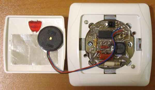
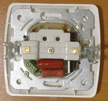
Controller design
The regulator is assembled on a single-sided PCB from foil fiberglass, the drawing and arrangement of parts which are in the attached files. The Board is designed for installation in wall-mounted single-button light switch VI-KO (models "Yasemin" or "Sigmap") from which you have removed unnecessary elements and is attached to the frame using screw d2.5mm. in the center. Under his hat, you need to put an insulating washer. On the reverse side of the lock nut as shown in palaemon photo.The sensor in the form of a cut from foil rectangle size 30x45 mm installed on the inside of the lid (which formerly served as the key) and fixed thereto by a transparent adhesive tape over the entire area, you only need to leave a contact pad for the spring. On the sides of the lid is glued strips of cardboard measuring 4 mm X30 mm. and a thickness of 0.5 mm. so she sat down on the seat with some effort. The piezo oscillator is attached to the lid using double-sided tape. The figures in the attached files shows the elements of the case after completion. The controller is located in the wall in existing standard indentation for the switch and is connected via a conventional two-wire circuit, no modifications are required. You must correctly connect the phase wire, as shown in the diagram, otherwise the sensor will not work.
The appearance of the assembled device.
Used parts and possible replacement.
To control the controller, you can use any remote control working on Protocol RC-5. The microcontroller DD1 replace on ATtiny2313-20SI or ATtiny2313V-20SU(SI), and a photodetector B1 similar, designed for a carrier frequency of 36 kHz, for example SFH506-36, TSOP1736, TSOP1836SS3V, but it should be noted that the pin photodetectors of different types may be different. As L1 used industrial reactor for surface mounting mark CDRH127/LDNP-101MC PBF (100 mH 1.7 A). It can be replaced with similar or improvised inductance 30 - 200 µh on the current consumed by the lamps lamp (0.5 A for every 100 watts).
Symmetrical thyristor VS1 may be from the part no bt137 - BT139 for a voltage below 400V or similar from another manufacturer with a small current management. Zener diode VD2 to replace 1N4734A, XA, XA. Instead of the led HL1 indicated on the scheme can be applied HB3B-446ARA or similar SuperBright red glow (when there is insufficient brightness can be reduced to 4.7 R14 n). The piezo oscillator can be replaced by open-frame type FML-34,7 T-2,V-100 or take any other similar wire of the so-called "self-driven", such as the call from the old telephone sets of Asian origin.
Easier of course to use a piezoelectric emitter with built in generator, for example HPA17A or HPM14A, but such could not purchase. In this case, the elements are set R10, R11, R12, R13, VT2, and a sound projector is connected to +5V and to the PD0 pin polarity. Instead of VT1, VT2, you can apply the types of transistors KT315(B,G,E), 2SС1015Y, KT3102 or similar. In this case, VT1 120<hfe<300, and VT2 hfe>200. Capacitors C1, C2 type K73-17 or similar imported a voltage lower than specified in the scheme. All resistors - MLT capacity indicated on the diagram. The ratio of the resistances R6/R4 should be close to the 0.8 - otherwise the detector will be zero wrong.
Assembly and adjustment of regulator
Accurately assembled regulator causing part of the setting is not nordana. You only need to program the microcontroller. Connect the programmer to the connector XP2 (standard six-slot for in-circuit programming of AVR microcontrollers). In this case, since the programmer to the controller should receive the voltage (the controller during the programming must be disconnected from the mains) . In prilagemyh files posted two firmwares: one realizewhat are touch-only, and the second both types of control within 5 minutes.(intended for operation check).
For a full featured firmware refer to to the author, This email address is being protected from spambots. You must have JavaScript enabled to view it. .
FUSE bits of the microcontroller DD1 must be programmed as follows:
• CKSEL3…0 = 0100 - synchronization from the internal RC oscillator 8 MHz;
• CKDIV8 =0 - clock divider included eight;
• SUT1…0 =10 - Start-up time: 14CK + 65 ms;
• CKOUT = 1 - Output Clock on CKOUT is prohibited;
• BODLEVEL2…0 = 101 - the threshold level for control circuit supply voltage of 2.7 V;
• BODEN = 0, the supply monitor is enabled
• EESAVE = 0 - erase the EEPROM when programming the crystal is prohibited;
• WDTON = 1 - No permanent enable Watchdog Timer;
The rest of the FUSE bits is better not to touch. FUSE-programmed bit, if set to "0".
Then you should read the calibration byte for the internal RC oscillator at 8 MHz and record it in the flash memory at the address 7FFh (last cell).
Instruction manual is in the attached files. The controller has a test mode on the remote control will work. For this you need to turn it on and set the minimum brightness, then press the remote control any button and if it works on RC-5, you will hear a sound signal duration of 1 sec. Allowable total power switched lamps - 400 watts. At most, you need to install the triac on a heat sink of adequate size.
The controller is designed to control only the active load. To connect it to other devices, such as fluorescent lamps or motors. This can damage the inverter. The regulator has good repeatability, all of the collected instances are earned immediately without any settings.
When assembling and adjustment of regulator remember that all of its elements are the AC line voltage and touching them may result in electric shock.
Download the project files in one archive
Author: Alexei Batalov, This email address is being protected from spambots. You must have JavaScript enabled to view it. , ICQ#: 477022759; Publication: www.mcuprojects.narod.ru/dimmerSIR/DimmerSIR.html, www.cxem.net