


")

The device for automatic switching of lights can be divided into three categories: simple logic IC's using RPSO and microcontrollers (MCU) Unlimited number of effects available only on machines the base ROM or MK, but to launch these devices in action radio Amateur needs positioning the computer and the programmer. Machines belonging to the first of these categories do not require programming, but sell usually a small number of lighting effects.
When developing this device, the objective was to maximize the number lighting effects using a minimum of elements. As a result managed to create machine on just four chip series K555, four switching led garland. Implemented such light effects as "running lights" from one, two or three of decorations and in the other direction, alternately enabling garlands and off in the same order and some others. Each of the effects the machine repeats a few times, then moves on to the next. In this case the entire cycle lasts long enough and does not bore the audience with monotony.
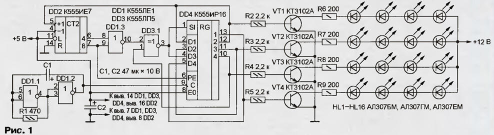
Diagram of the device shown in Fig. 1. It is based on four-digit register shear with parallel loading KIR (DD4). The node control register consists of binary counter CIE (DD2) and logic elements DD1.3 and DD3.1. The effect of "running lights" is achieved in one direction at the expense of ordinary shift code in the register in reverse - parallel entry in the register of its output signals with a shift by one digit.
(click to enlarge)
The master oscillator of the machine is assembled on the elements DD1.1 and DD1.2. Frequency generated impulses is 3…4 Hz. You can change the selection of the values of resistor R1 and capacitor C1. Garlands control keys on the transistors VT1-VT4. In addition to these in the scheme CTSA, here you can set almost any patterns transistors n-p-n low or medium power.
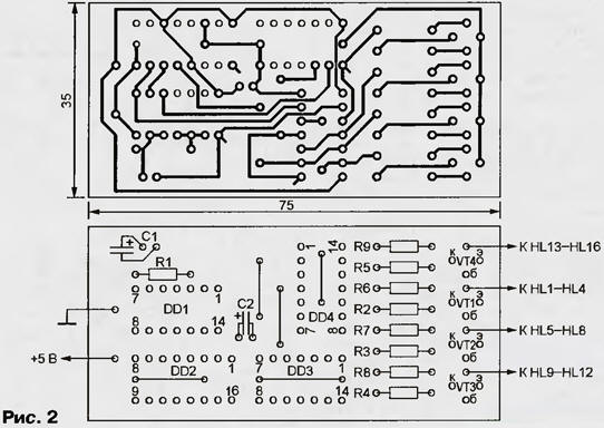
The printed circuit Board and the circuit arrangement of the switch elements garlands it is shown in Fig. 2. Wire jumpers located under the chip, must be set before mounting the last on a charge. All chips can replace them with functional equivalents from series K155 or KR1533.
Each garland consists of four series-connected LEDs arbitrary emission color. If necessary garlands of a larger number LEDs have to increase the voltage of their power supply (+12 V) at the rate of 2 3 In… each led and to select values of resistors R6 - R9. The voltage must not exceed the allowable for the transistors VT1 - VT4. When the desire instead of the led you can use garlands of bulbs and feeding them from a network 220 In, but this would require the keys on thyristors or triac and, preferably, with galvanic isolation of control circuits from power. Schemes such keys have been published in Amateur radio literature.
Author: Yuri Kuznetsov, Staraya Russa, Novgorod region.