


")

High-brightness white light emitting diodes - economical low-power emitters of light that can successfully replace in flashlights and incandescent lamps. In recently went on sale led lights industrial manufacturing. This article will help Amateurs make their own like this and, at the same time, to understand some of the intricacies of power LEDs.
Feature of led as a load for the power source is misrepresented that he, unlike incandescent bulbs, has a nonlinear current-voltage characteristic with pronounced "'heel" in the initial part. Forward voltage drop on the white led light when working currents exceed 3 V. to Nourish it from the battery voltage of 4.5 V from three battery cells is irrational - a third of the energy will be spent in vain, scattered on the quenching resistor. Voltage two, and even more from one galvanic cell is insufficient you want a Converter that increases the voltage to the desired value and support it constant when the battery is flat.
Such a Converter can be collected according to the scheme shown in Fig. 1. It is based on chip MACH company "Maxim" designed specifically for portable electronic devices with Autonomous power supply. The Converter saves efficiency by reducing the supply voltage to 0.7 V. Stabilized the output voltage can be set to 3.3 or 5 V when the output current accordingly to 300 or 200 mA. Efficiency at maximum load is more than 87 %.
DA1 chip included in the model scheme. The inductor L1, the diode VD1 and the capacitor C3 together with a built-in chip field effect transistor (the drain is connected to the pin 8, the source - pin 7) form a key inverter step-up type. Capacitor C2 blocks the alternating current source model voltage, and C1 - GB1 battery. The feedback voltage from the output of the inverter goes to pin 6 of the chip. The diagram shows the connection of pin 2 match an output voltage of 3.3 V. If we combine this conclusion with the General wire (pin 7), the voltage will increase to 5 V. the Connection with the common wire output 1 will stop the inverter. Pin 5 - input not used in this case control system supply voltage. He should not remain free and this reason is connected to the battery positive GB1.
The cycle of operation of the inverter can be divided into two phases. In the first inner the transistor is open, through the inductor L1 flows linearly rising current. Magnetic field of the inductor accumulates energy. Diode VD1 is closed. The capacitor C3 is discharged, giving the current in the load. Nominal phase duration is 5 MS, but it can be automatically terminated earlier if the drain current of the transistor reaches the maximum valid values are (approximately 1 A).
In the second phase of the cycle the transistor is closed. The current of the inductor L1, the current now, dropping, using the VD1 diode charges the capacitor C3, compensating for his discharge in the first phase. The voltage on the capacitor the threshold phase is terminated. In depending on supply voltage and load current repetition frequency described cycle varies in very wide limits.
With the decrease of the input voltage and the increase of the load current IC MAG switches to fixed duration of phases (respectively 5 and 1 μs). The output voltage is not stable, it decreases being maximally possible in such conditions
As a light emitter in the light has four LEDs L-53PWC "Kingbright" connected in parallel. Connector X1 is available in the lamp tube cartridge. Since the current 15…30 mA forward voltage drop across the led approximately 3.1 V, the extra 0.2 V had to be put on the resistor R1 included consistently. With the heating of the LEDs, the voltage drop on them is reduced and a serial resistor in some way stabilizes the current and brightness glow. To align the value of the current through the individual LEDs are not necessary. The differences in their brightness by eye is not detected.
The basis for the design was taken a flashlight "VARTA" with swivel light-emitting unit. In principle, any other suitable lamp, which there's space to accommodate the necessary details. Thanks the use of small components all managed to place inside light-emitting site (Fig. 2). The installation was carried out in hinged manner with the use of pins as reference points.
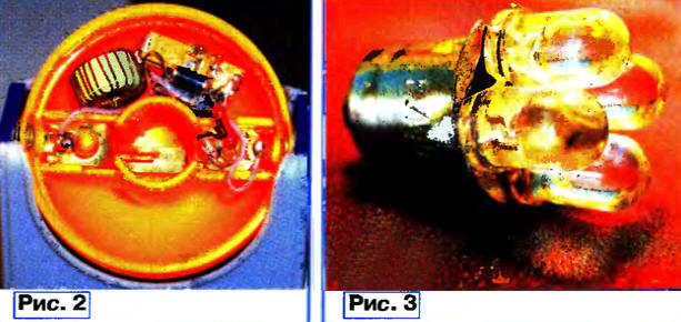
Four LEDs, as shown in Fig. 3, took the place of glass remote bulb standard lamp lantern. The conclusions from these anodes are soldered to the metal shell the cap, the findings of the cathodes are omitted in its Central hole and soldered.
Oxide capacitors C1 and C3 - import tantalum surface mount. Their low series resistance has a positive effect on efficiency. Capacitor C2 - K10-176, or any other ceramic. The 1N5817 diode with a barrier of a Schottky can replace SM5817 or neglecting a bit large direct voltage drop, on 1N5818 (SM5818). Winding of the inductor L1 - 35 turns of wire sew-2 0,28, wound on the magnetic core of inductor of low-power line filter a pulsed power source. This ring is size of molybdenum CHH permalloy magnetic permeability 60. You can use chokes inductance 40… 100 µh and the allowable current of 1 A or series with DM core magnetic circuit. It is desirable that the active resistance of the winding throttle does not exceed 0.1 Ohm, otherwise the efficiency of the device significantly reduced.
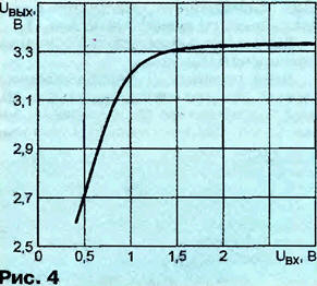
Opportunities made voltage Converter have been tested with the use of an adjustable voltage source 0…3 In instead of the battery GB1. Removed the dependency of the output voltage from the input shown in Fig. 4. The transmitter continued to operate even when the supply voltage to 0.4 In giving in this mode, the voltage of 2.6 V at a current of 7 mA (instead of the original 110 mA). The illumination of the LEDs were still visible. After turning off and re-enable the Converter was run only at supply voltage more than 0.7 V. the Measured efficiency when fresh batteries were 87 %.
Maxim company, today launches an improved version of the chip MACH - MAH. It has a built-in synchronous rectifier, making unnecessary external diode and giving the opportunity to increase Converter efficiency up to 94 %. Should keep in mind that to achieve such a high efficiency is possible only with proper choosing the type and values of external elements and thoughtful installation Converter.
Author: B. Rudenko, Novosibirsk