


")

This device is intended for both local and remote control of lighting, using standard electroset ~220v 50 Hz. It contains two independent channels of control, in which any combination can work in one of two modes:
1. The mode switch. In this mode, when you turn right is served 100% of the mains voltage to the load. It is used to energosberegayuschih lamps.
2. The mode of the controller. In this mode, the load power can be adjusted continuously. Used for such consumers such as incandescent lamps or halogen lamps (including powered via an electronic transformer).
Remote control switch is carried out by four buttons (two on each channel) of any remote control that works with widely used system command RC-5. Consoles of this system is quite affordable and cheap.The advantages of this switch:
Through the use MOSFET transistors instead of ICS, there is no such thing as the "holding current" and therefore, the control range is not bounded from below for any admissible load power
The ability to manage in a wide range of power consumption: 1 W to 400 W (when mounting the transistors on taprooted)
Switching of loads occurs at the moment of transition of the mains voltage through zero, thereby minimizing the interference to the grid. Therefore there is no need for suppression elements in the switch.
For the mode of the controller it is possible to set individually for each channel low threshold power control. This can be useful for those devices that cannot be lowered below a predetermined value (e.g. electronic transformers for halogen lamps)
The functions performed by the switch:
Remote switching on and off load, the power adjustment;
Local on, off and intensity control by using the control buttons
In the controller mode smooth on that prolongs the service life of incandescent lamps
Remembering the previous state of the switch and the power level (failure elektropitanie work is restored). By dynamically using EEPROM for these functions, the resource to the amount of manipulation of the control switch for each channel is at least 3 million times.
Management controller
Local control is located on the switch, two buttons (one for each channel)
Enables or disables load - single pressing briefly (0.2 to 1 sec.).
Regulation of power - holding down the key more than 1 sec. Each long press invokes the opposite direction of the power change.
Remote control is a remote control aimed at the side of the switch. To manage the switch are determined by the four keys of the keypad.
Turn on or off the load - a single short press the corresponding key of the remote control (0.1 to 1 sec.).
Regulation of power - holding down the key more than 1 sec.
When clicking on control keys local control or remote control beeps with a duration of ~0.2 sec., indicating that the command was accepted.
Device switch
The controller is built on cheap and affordable microcontroller АТtiny2313-20PU. Schematic diagram of the device is shown below.
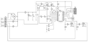
(click to enlarge)
Supply unit serves to provide the microcontroller and the infrared receiver supply voltage close to 5 V. the Input voltage is rectified through a diode bridge VD1, is extinguished by the resistor R1, is limited by the Zener diode VD2, resulting in C1, C2 generates a voltage of about 5V. Elements R2C3 are the filter in the power supply circuit of the photodetector.
The synchronization host. R6R7R8C4 chain is required for the detection of zero. Resistors R6R7 extinguish the input voltage, which is limited by internal diodes PD2 pin of the microcontroller. The capacitor C4 serves to suppress impulse noise. Worked through each transition of the mains voltage through zero - 100 times per second. If the desired and current capacity are not the same, the current is adjusted. It also allows you to implement smooth on the load in the controller mode. So twice the power supply frequency is used to poll the local control buttons, the formation time interval of the illumination of the HL1 and HL2.
Nodes of control and indication. SB1 and SB2 buttons are used to control the first and second loads, respectively.
LEDs HL1 and HL2 serves to indicate the operating modes of the first and second control channel.
The photodetector B1 receives IR packages from the remote control. It also happens demodulation carrier frequency of parcels RC-5 (36 kHz). The generated output signal of the photodetector is input to РD3 microcontroller. Decoding IR parcels in MK are programmable. Analyzing code adopted team, the microcontroller DD1 generates control signals for the power transistors. Audio system HA1 and LEDs HL1, HL2 signals at certain States of the controller in different modes.
Node switching of the load. With output PB0(PB1) of the microcontroller DD1 positive impulses through R9(R10) open the transistors VT1(VT2), through which the supply voltage is supplied to the corresponding load. Resistors R11 and R12 serve to prevent spontaneous opening of transistors at the time of supplying power to the device when the findings PB0, PB1 are in the third state and is not configured by program MK. The load receives the rectified mains voltage, which is valid for used lamps.
The mode selection is done with jumpers S1 and S2 for the first and second channel respectively. If the jumper is missing, the channel is in the controller mode, and if set, then switch.
Controller design
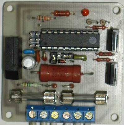
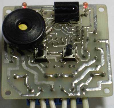
The regulator is assembled on a single-sided PCB from foil fiberglass, the drawing and arrangement of parts which are in the attached files. By printed conductors installed elements HL1, HL2, B1, SB1, SB2, HA1. The remaining elements are mounted on the opposite side. Board mounted with screws D2.5mm at the corners. Power transistors are specifically placed at the edge of the Board so that they can easily attach the radiators, if used, the load consumes more than 100 watts.
Used parts and replacement
To control the controller, you can use any remote control, working on Protocol RC-5. The microcontroller DD1 can be replaced by ATtiny2313-20PI or ATtiny2313V-20PU(PI), and a photodetector B1 similar, designed for a carrier frequency of 36 kHz, for example TSOP4836, TSOP1836SS3V, SFH506-36, SFH5110-36, TFMS5360, but it should be noted that the pin photodetectors of different types may be different. Transistors VT1,VT2 can be IRF840A or domestic counterparts KB, KB, but it should be noted that all of these transistors unlike 2SK2545 the mounting surface of the heat sink is isolated from the drain, so to mount them on a common heatsink only through the insulating gasket. Zener diode VD2 to replace BZX79C5V1, BZX55C5V1, 1N4733A, or you can pick up domestic XA,G XA,G, so that the voltage stabilization does not exceed 5.5 V. Instead of LEDs HL1 HL2 you can apply HB3B-446ARA, ARL-3214URC-10cd or similar SuperBright. Diode bridge VD1 must be rated current not less than the total current consumption of both loads and reverse voltage of not less than 400B. HA1 - any twin piezo Squeaker. The fuse holders used brand FH-100. The fuses protect the power components from peruski and short circuit protection. The value must be 2.....2.5 times higher than the current consumption of the used load.
Assembly and adjustment of regulator
At the beginning of the charge on sealed all items except DD1, B1, C4. Turning the knob to the network, measure the DC voltage on C1 and then on C3. In both cases, it should be about 5V. Then close the jumper tracks on the Board, going to 20 and 5, 20 and 4 conclusions DD1, should light HL1 and HL2 respectively. Now we need to check the operation of control channels. For this we need to turn off the power, connect as loads, such as lamps filament to the power of 100 watt, power left to apply for the scheme conclusions R9, R10 c node power +5V (for example by circuit jumper the PCB track leading to 20 and 12, 20 and 13 conclusions DD1. This should light the lamp first and second channel respectively. If all goes well, then disable the controller from the mains, sealed DD1(although it is better to put the socket) and B1, C4, and connected the programmer to the connector XP2 (standard six-slot for in-circuit programming of the AVR). In this case, since the programmer to the controller must reach the supply voltage. The firmware files to verify that the controller is attached (to flash EEPROM also a must!!!)
FUSE bits of the microcontroller DD1 must be programmed as follows:
• CKSEL3…0 = 0100 - clock from internal RC oscillator 8 MHz;
• CKDIV8 =0 - clock divider included eight;
• SUT1…0 =10 - Start-up time: 14CK + 65 ms;
• CKOUT = 1 - Output Clock on CKOUT is prohibited;
• BODLEVEL2…0 = 101 - the threshold level for control circuit supply voltage of 2.7 V;
• EESAVE = 0 - erase the EEPROM when programming the crystal is prohibited;
• WDTON = 1 - No permanent enable Watchdog Timer;
The rest of the FUSE bits is better not to touch. FUSE-programmed bit, if set to "0".
For the mode of the controller, as mentioned above, can be set individually for each channel low threshold power control. For this, the cells in the EEPROM at address $01 and $02 to record the value for the first and second channel respectively. In this device range from 0% to 100% there are 127 degrees of regulation. Thus, to set the lower threshold level, for example, 25% need the value to be multiplied by 1.27 (25*1,27=32) and record the value 32($20) to the corresponding cell of the EEPROM. Initially in both cell zeroes.
Instruction manual is in the attached files. The switch has a test mode on the remote control will work. You'll need to set both channels in the regulatory regime to enable them to set the minimum power level off. Then click on the remote any button and if it works on RC-5, it will beep duration 1sec. Allowable total power switched load in each channel without radiator - 100 watts. If greater, you must install the transistors on the heat sink of adequate size. The controller is designed to control only those types of loads that are specified in the beginning of the article. They allow the power of the rectified mains voltage. To connect it to other devices, such as fluorescent lamps or motors. This can damage the inverter.
Attention! When assembling and adjustment of regulator remember that all of its elements are the AC line voltage and touching them may result in electric shock.
Download the project files in one archive : scheme, demoralise, drawings, printed circuit Board, operating instructions
Author: Alexei Batalov, This email address is being protected from spambots. You must have JavaScript enabled to view it. , ICQ#: 477022759; Publication: www.mcuprojects.narod.ru/projects.html, www.cxem.net