


")

It is known that on the night lighting of entrances of houses spent a huge amount of electricity, and the majority of the time the lights are on nothing. To avoid unnecessary energy consumption, you must equip the entrances of houses machines, including for a short time the light only when necessary. Below are drawings of two variants of automata stair lighting.
The scheme is the first of them is shown in Fig. 1. Assume that power is applied to the device, and the capacitor C2 is discharged. Zener diode VD2 and a composite transistor VT1VT2 close; to the base of transistor VT3 is fed through resistor R3 to a positive voltage, which opens the transistor. In the circuit of the control electrode of SCR VS1 flowing current, the SCR is open and the floors are lit lighting lamps (they are marked EL1). As the charging of the capacitor C2 through the resistor R2, the voltage across its plates is increased. When it reaches a voltage stabilizing Zener diode VD2, last open, then open the transistors VT1, VT2, and VT3 transistor is closed. SCR VS1 is also closed, and the lights dim EL1. In this state, the device is the most time consuming from the mains current is about 2 mA. For the lighting, you should press the SB1.
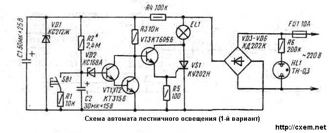
All of the elements of the device, including lamps and lighting, feed the rectified voltage taken from the diode bridge VD3-VD6. The voltage necessary for the operation of a transistor switch and to charge the capacitor C2 (about 12 In), is obtained at the output of the parametric stabilizer VD 1 R4. The capacitor C 1 smooths out the ripple voltage. Resistor R1 limits the current discharge of the capacitor C2 when the button SB1. Furthermore, the presence of this resistor increases the safety when using the device in the event of a breach of isolation button SB1.
Supply voltage to the control electrode of SCR VS1 with its anode (through the open transistor VT3) allows the flow of current in the circuit of the control electrode until the moment of turning on the SCR, i.e. within a fraction of a millisecond at the beginning of each half cycle. As a result, on the VT3 transistor dissipates very little power.
Neon lamp HL1 installed next to the button SB1, that it can be easy to find in the dark. The same buttons installed in the stairwells floors and connect them in parallel. Corresponding neon lamps connected to the network via the resistors 200 ohms (- R6).
The maximum total power of lamps which can be operated with automatic stair lighting is 2 kW. SCR VS1 must be installed on the radiator with the cooling surface of about 300 cm2, diodes VD3-VD6 - four radiators with an area of 70 cm2 each. If the load does not exceed 300 W, SCR and diodes to be installed on the radiators are not required.
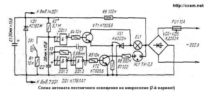
In Fig. 2 is a diagram of a second embodiment of automatic stair lighting, which used a chip CLA. The voltage of the capacitor C2 is supplied to the inputs of the logic element DD1.1. Until the voltage on the capacitor is less than the voltage switching threshold of the element at its output a high voltage level, which opens the transistor VT1. This opens SCR VS1 and voltage is applied to the lights EL1. In the further charging of the capacitor C2 logic element DD1.1 switches, its output appears low voltage level, the transistor VT1 and SCR VS1 is closed and the lamp will extinguish.
Publication: www.cxem.net