


")

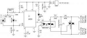
This is the 200W lamp flasher circuit diagram. The frequency/speed of the lamp flashing can be adjust with the range of 1Hz to 5Hz. You can use the PR1 variable resistor (trimpot) to adjust the flashing speed. The duty cycle of lamp flashing can be adjusted using PR2 variable resistor.
The DC input power supply range is 6V to 12VDC. The main AC supply is about 230V. The output lamp to use is upto 200W lamp / bulb load. The recommended load is about 100W, but it said can be used for up to 200W. Don’t use the load higher than 200W lamp.
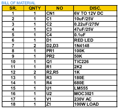
Components list:
PCB design layout:
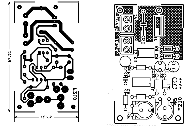
The PCB dimensions is 36 mm x 68 mm. If you want to mount the circuit on a case or fixed plate, then the four mounting holes of 3.2 mm each is required.
The power battery terminal and DC supply port is used for easy connecting the circuit to its supply and input/output.
The following is the looks of the kits.

200W Lamp Flasher circuit source: iq-technologies.net