


")

Circuit diagram:
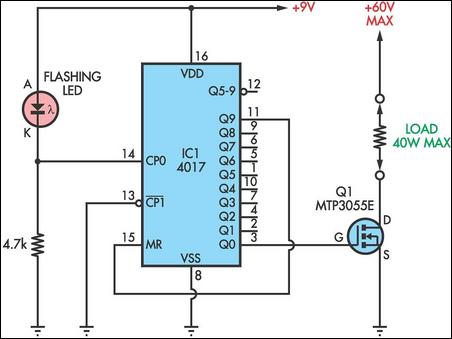
One Of Nine Sequencer Circuit Diagram
Uses for the circuit include sequencing different strings of Christmas lights etc. The resistor from CP0 to ground can be anywhere from about 330O to about 10kO. Lower values will cause the LED to flash more brightly if that is required. With a 4.7kO resistor as shown, the clock input CP0 (pin 14) will alternate between about 2V and 7V. To drive loads of up to 40W at up to 60V, connect each output to the gate of a 2N3055E or equivalent Mosfet (MTP3055E etc), as shown for Q0.
Author: Peter Olsen