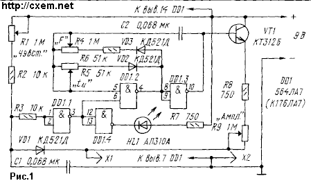
Scheme one of the stimulants shown in Fig. 1. Main the details of his - IC series 564 or C, led indicator HL1 and the transistor VT1, which made matching (buffer) cascade. In addition, the stimulator is supplied with test leads X1 and X2, where X1 is considered active - they drive on the body and find the desired point, and x2 - passive, attachable, for example, to the arm.

On the elements DD1.1, DD1.4 assembled the determinant of biologically active points (BAP), and DD1.2, DD1.3 - generator stimulating pulses. In contact with the probe X1 active point the resistance of the human body in this place falls sharply, in the resulting input element DD1.1, and hence the output DD1.4, appears almost level logic 0. Found point informs the lightened led HL1.
At the same time appeared on the exit of the element DD1.1 level a logical 1 enables the generator. Produced by them the pulses pass through a matching stage and do the active probe X1, and through him - on the patient's body. Diode VD1 prevents the passage of pulses to the input of the element DD1.1 and at the same time, in the pauses between pulses allows save search mode BAHT. Thus, there is no the need for the button characteristic for such stimulants and switching probes from the search mode points in the mode of stimulation.
Variable resistor R1 set the threshold trigger automation individually for each patient, resistors R4 and R5 the frequency and the duration of the stimulating pulses, and a resistor R9 is their amplitude.
Parts of the device can be placed in a small metal pencil case, serving at the same time passive probe. For the manufacture of active probe exhaust will fit his ball-point pen, for the writing node which solder wire, and in the case if necessary, pour drug - then procedure stimulus will be combined with electrophoresis (health method of influence on the body by direct current and drugs, enter through the skin or mucous membranes).
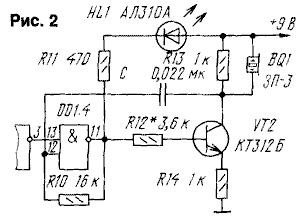
If, in addition to light, need and sound display search BAT, the stimulator should be refined as shown in Fig. 2. Cascade on the transistor VT2, together with cascade on the element DD1.4 form generator AF signal which is converted into sound piezoelectric emitter BF1.

Should notice that in the generator pulses of the stimulator in the frequency a bit changes the duration of pulses, and in the regulation duration - frequency.
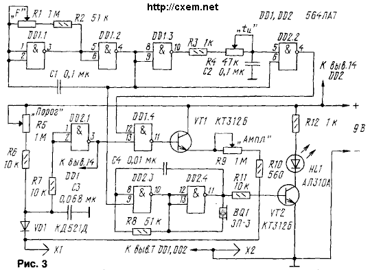
In Fig. 3 given another scheme stimulant, which the pulse generator is made otherwise, thus avoiding the mutual influence of frequency and the duration of the pulses. Except also, it feeds the generator on the elements DD1.1 - DD1.3 from the element DD2.1.

Generator light and sound signals, performed on the elements DD2.3, DD2.4, a modulated signal generator stimulating pulse - this allows visually and aurally to control the frequency stimulation pulses.
When the values of the elements specified the diagrams of stimulants the frequency of the pulses can to change a variable resistor 10 to 150 Hz, and the duration is from 0.5 to 5 msec.
Attention! The device to be used after consulting a doctor!
Author: A. Boroday; Publication: www.cxem.net


