


")

Diagram of the device shown in Fig. 1.
Multivibrator to trigger DD1.1 is the reference generator. Repetition frequency of the pulses depends on the values of elements time-setting circuits R3C1 and R4C2. Resistors R1 and R2 only prevent the overload outputs of the trigger discharge current of the capacitors C1 and C2 and the frequency not affected. Duty cycle (in this case approximately equal to two) plays no role and can be any, as the trigger DD1.2 changes its state only at the time of change of the low level to the counting input of the high. Therefore, the duration of the output pulse of the trigger DD1.2 always remains in exactly equal to the duration of pauses between them.
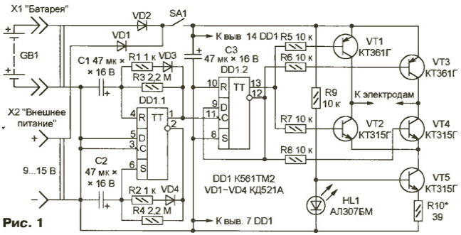
Two antiphase pulse sequences taken from these outputs, control switch on the transistors VT1-VT4, periodically changing the direction of current ow through submerged silver electrodes. Current stabilized transistor VT5. An exemplary stabilizer is a direct the voltage drop across the led HL1.
Feed device from a galvanic battery GB1 voltage 9…15 V or external source (via connector x2). Diodes VD1 and VD2 automatically switch the appliance on the sources whose voltage is more. They protect against erroneous the polarity of the supply voltage.
The device is assembled is shown in Fig. 2 single-sided PCB. Used resistors MLT-0,125, capacitors C1, C2 - K53-4, K53-10 or other oxide with low leakage current, C3 - oxide of any type, for example, K50-35. All the diodes can be replaced by other low-power silicon. Instead of transistors CTG suitable KT3102 with any letter index, and CTG will replace CT also any index. The switch SA1 - PD9-2, sockets X1, x2 - CP-SH-5-16, but it is possible successfully applied and other suitable size.
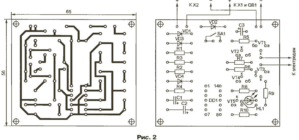
(click to enlarge)
The electrode holder is the same as in the original version of the instrument. He is a "blade" made of organic glass with a thickness of 4…6 mm, which with two sides pasted plates with an area of approximately 1 cm2 of silver (net technical or jewellery of the highest standard). The soldering joints to the plates of the electrodes the connecting wires must be above the water level.
The collected charge is placed in the body of a suitable size. It can accommodate and the battery GB1. When creating a device collection R10 set the current in the circuit of the electrodes is equal to 16 mA. With the high current performance of the device - 1 mg of dissolved silver in a minute. Knowing her and the amount of water in the vessel, it is easy calculate desired to obtain the desired concentration of the metal length processing.
The current stabilizer can be collected on the integral stabilizer CRES as it is shown in Fig. 3 by excluding from the scheme (see Fig. 1) the resistor R9, led HL1 and the transistor VT5.
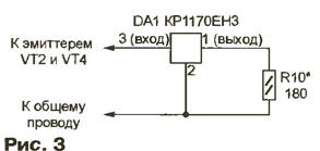
The current is set by resistor R10.
Author: V. Sorokov, Sergiev Posad, Moscow region.