Active bandpass filters in comparison with have substantial passive the advantages, especially at low frequency, because they allow you to refuse coils having in this frequency region large dimensions, and in many other characteristics are far from ideal. High resistance and stability has active biquadratic filters mode a bandpass filter to obtain the value of the quality factor exceeding 100. Typical scheme such a filter built on operational amplifiers shown in Fig. 1.

In biquadrates filter summing integrator subtracts the output from the input the voltage of the lowpass filter (they are shifted in phase by 180 deg.)- On frequency below the transition zone, these signals are mutually compensated and the output signal is considerably weakened. When it increases, coming out of transition phase, decreasing the output signal of the integrator't already compensates for input, so the output of the filter, the signal level increases. When further increasing the frequency rolloff of the integrator provides attenuation of the output signal and completes the formation of the frequency characteristics of a bandpass filter.
The lack biquadratic filter - increased number of active elements. Promising in these conditions it is possible to consider the use as an active elements of CMOS inverters that can operate in linear mode and have before operational amplifiers a number of advantages, for example, the lack of inclination delays, increased operating frequency. And the cost is usually is lower.
Among the shortcomings are considered active elements will celebrate their little gain (30...50 dB). However, given that biquadrate filters do not require high requirements to gain, this drawback is not an obstacle for the application of CMOS inverters as active elements.
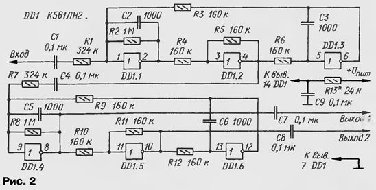
One of the most common circuit structure CMOS - K561LN2 - contains in one case, six inverters, allowing you to build bandpass filter the fourth order. The scheme of such a filter obtained by cascade connection two filters of the second order shown in Fig. 2.

It is easy to see that both second order filter are identical and structure similar to a standard filter at the shelter (see Fig. 1). In the filter there are two output signals which are antiphase.
The current consumed by the filter, set by selection of resistor R13. In this case the supply voltage may vary in the range 5...15 V. current reduction power increases the gain of the active filter elements, but worsen them frequency properties and increases the output resistance. Optimal should to consider the current consumption in the range of 0.5-2mA.
When specified on the diagram the values of the filter has a center frequency fo=1000 Hz, bandwidth Δf=100 Hz, the gain is KP=10. For other options the filter can be calculated by the following method.
Put for the input link of the C2=C3=C and R3=R4=R5=R. let us Calculate R, R1 and R2: R=1/(2πf0∙C); R1=Q/(2π∙f0∙C)∙√KP; R2=Q/(2πf0∙C); Q=f0/Δf', where Δf'=Δf/v2-n, where Q - quality factor of the filter; n is the number of cascade-connected units of the second order.
The filter allows independent tuning of the parameters, if necessary. So, the center frequency fo of the input level can be adjusted by selection of the resistor R3, Q - R2, the gain is KP - R1.
The operating frequency of a filter constructed on the inverter chip K561LN2, maybe to reach into the hundreds of kilohertz. The use of similar chips series CR, AS, NS will allow to increase the operating frequency 10...15 times.
One of the features of the considered filter is that the width of the strip transmission when you change the center frequency remains unchanged. In addition, when R1=R3 the gain of the link is determined by the ratio R2/R1. Input the resistance element is more than the resistance of the resistor R1, the output is 10... 15 ohms. Final amplifying active elements may lead to some increase figure of merit in comparison with the calculated value.
The results of modeling have confirmed the ease of regulating filter, good the actual properties of a design and their high stability.
Literature
Falkenberry L. Application of operational amplifiers and linear IC (transl. from eng.). - M. Mir, 1986, 598 S.
Author: D. Onysko, Novocherkassk, the Rostov region.


