


")

The proposed generator of radio frequency signals (RF) can be used to settings antennas Amateur radio stations. It will be helpful in establishing receiving and transmitting equipment.
Hams for "quiet" settings of connected antennas (without transmitter) developed various RF generators, which are used to power devices bridge and panorama types. Typically, these generators are collected by classical schemes based on resonant circuits. Frequency tuning has been performed either by a variable capacitor, any change in the capacitance of the varicap.
These generators are hard to produce because they contain inductors. But most importantly - when tuning around the band changes the level of the output the signal that leads to the need to adjust the level before each measurement.
Control voltage, Frequency, MHz 2,62 20 2,8 25 2,98 30 3,12 35 3,29 40 3,46 45 3,66 50These circumstances have prompted the search for unconventional ways of generating radio frequency (RF) oscillation sine wave using digital chips wide application. Most suitable chip was CGG, which is capable of generating sinusoidal oscillations in the frequency range 15…60 MHz at a constant signal level at the output.
The radio frequency generator (Fig. 1) is designed to power SWR meter bridge and panorama types, gauges AFR. The range of its restructuring 20…50 MHz, power on 50 Ohm load - not less than 200 mW.
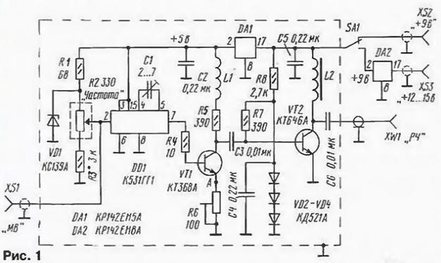
The remote master oscillator (MO) on the chip DD1. Transistors VT1 and VT2 are made wideband amplifiers. Frequency ZG depends on the voltage, remove from engine potentiometer R2. Depending on the capacity of the capacitor C2 and the resistance of the resistor R3 are two possible modes of generation: broadband in the range of 20…50 MHz (in this case, the resistance of the resistor R3 should be 470 Ohms) and narrow-band with a bandwidth of 5 MHz (for example, 45…50 MHz), in this case, the resistor R3 must have a resistance of 3 ohms. To obtain a different range of adjustment you must include an additional resistor between the upper circuit on the output of R2 and cathode VD1.
The dependence of the frequency on the control voltage at pin 2 of chip DD1 shown in the table. This dependence is almost linear and has a slope adjustment of 20.8 MHz/V. Therefore, the frequency setting can be made by external digital millivoltmeter connected to the connector XS1.
The signal output from the chip DD1 is supplied to the base of transistor VT1. Load this stage serves the resistor R5 and corrective inductance L1. Trimmer resistor R6 to adjust the output level.
Feature stage amplifying transistor VT2 is to stabilize the current base (resistors R7, R8, diodes VD2 - VD4). Such circuit design reduces influence of load on the output level and removes the pressure of the cascade in the load loss.
The power generator may be exercised as from the source of voltage 12…15 In (on-Board network of the vehicle or the power supply of the transceiver) via the XS3 and from the battery compartment portable radio with a 9 V (connector XS2). This can be convenient when working in field conditions, for example, near antenna on the roof of the building. Current consumption of 150 mA.
Variable resistor R2 is the act-1 group And Vernier device, trimming resistor R6 - SDR-386. the rest - MLT-0,125. Trimmer capacitor C1 - PDA (CT-23), the remaining MILES. Coil L1 - frameless wound wire sew 0.31 mandrel with a diameter of 4.5 mm and contains 10 turns. L2 - unified choke DM-1 inductance 10 µh. High-frequency connector XW1 - SR-50-PV. XS1-XS3 - any low frequency. SA1 - small toggle switch has two positions.
The generator is mounted on a circuit Board of one-sided glass fiberglass, a sketch of which is shown in Fig. 2.
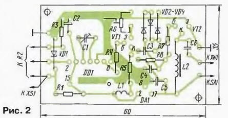
Board is placed in metallic screen. The device can be designed as stand-alone design or be part of another device with which it is supposed joint work.
The assembled generator begins to work immediately. The establishment is to install the desired range of frequencies by means of trimmer capacitor C1 and selection resistor R3. Then it is necessary to remove the dependence of the generated frequency from the Manager voltage. This will require a digital frequency meter and multimeter.
The device can perform the function generator sweep frequency when applying for connector XS1 voltage sawtooth shape. It is also easy to implement frequency modulation, if served on ХS1 audio signal, and amplitude modulation (for this we need to file a 3H signal at point "A").
In the author's version generator is configured to range 25…30 MHz and is hosted in one case with a bridge SWR meter.
Author: B. Tatarko, Tver