


")

Stations operating in УSW range 144… 146 MHz the transceiver or receiver "civil" CB band (27 MHz) required Converter. If your CB transceiver frequency, the Converter can to do with a fixed local oscillator (lo) This version of the Converter was proposed already the readers of "Radio" (I. Nechaev. "Converter for 144 MHz for CB radio station". Radio, 1999, No. 2, pp. 57, 58). If the transceiver has only one or two fixed operating frequency (e.g., radio station "Ural-R"), require a Converter with a tunable local oscillator.
Diagram of the Converter shown in Fig. 1.
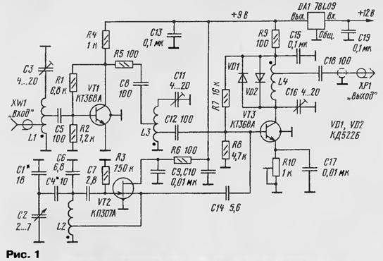
Transistor VT1 is assembled UHF, the transistor VT2 - heterodyne, and VT3 - mixer. All of these nodes are powered from the voltage regulator on the chip DA1, so the power supply Converter, you can use any source with a voltage of 12…30 V. Works Converter as follows. The received signal from the antenna via connector XW1 is delivered to the input circuit L1C3, where it is pre-frequency selection. Amplified by the transistor VT1 signal is supplied to the second RF circuit L3C11 and then to the input of the mixer, the base of transistor VT3.
The lo signal through a capacitor C14, is also fed to the input of the mixer. The restructuring of the local oscillator frequency is a variable capacitor capacitor C2. The difference signal, the dedicated circuit L4C16 with parts of turns of the coil appear on the output of the Converter, connector HR. To protect the Converter elements from the signal i own CBS radio transmitter are diodes VD1 ,VD2.
In the Converter you can use the following details: transistors VT1 ,VT2 - CTA, VT3 - CPU, diodes - any small-sized silicon. Capacitors: variable capacitor C2 - air-dielectric, preferably with a Vernier; trimmers - CT-25; constant - KLS, K10-17, km. Fixed resistors - MLT, S2-33, R1-4, trimmer - SDR-19. All coils of the Converter (except L4) are wound round wire sew-2 0,8 mandrel with a diameter of 5 mm. L1 - contains 4 coil with taps between 1.5 and 2 turns; L2 6 turns taped from 1.5 turns; L3 - 4 with loop taps between 1.5 and 3 turns. Coil L4 contains 25 turns of wire sew-2 0.2 s a branch from the 5th round.
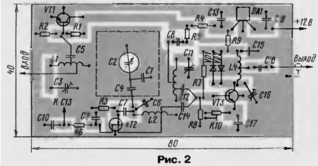
Most parts of the Converter are placed on the PCB from double-sided foil fiberglass, a sketch of which is shown in Fig. 2. Second the left side of the Board metallized and connected to the foil on the edge of the Board the common wire of the first party. Charge is placed in a suitable metal housing size. Input RF connector XW1 is set on one of the side walls of the housing. The output signal of the Converter is input to the CBS radio station via the RF cable fork JR not the end.
Establishing device begin with installation of frequency and the tuning range lo. This operation is carried out by selection of capacitors C1, C4 and small limits, pushing the coils of the coil 12. If, for example, the Converter will be operated with the radio station, operating at a frequency of 27.2 MHz, to obtain the range of accepted frequencies 144,5..to 145.8 MHz, which allowed to work with FM, the frequency of the local oscillator needs to be reconstructed within 117,3…to 118.6 MHZ. Setting the local oscillator frequency should be made with some margin around the edges range. Then the capacitor C16 tune the circuit L4C16 frequency CBS radio stations, and capacitors C11, C3, respectively, contours L3C11, L1C3 at the center frequency УSW range. Taking weak signals radio stations a trimming resistor R10, to the best reception quality, install the maximum transmission rate of the mixer.
After the initial setup, all coils should be lubricated epoxy glue, and then to have a final configuration of the Converter
Gathered by the author model of the device had a transfer ratio of 30 dB, which allowed in conjunction with radio station "Ural-R" with sensitivity 1 2… mV, resulting in a sensitivity of 0.18 0.2 mV.... The current consumed Converter - 15 mA.
It should be noted that the stability of the local oscillator frequency will be low, but for reception of FM signals with a satisfactory Increase by the use of ceramic frame for the coil lo and the selection of TKE contour capacitors.
Author: I. Nechaev (UA3WIA)