In the directory of foreign firms producing semiconductor devices and selling them, appeared the so-called "Blinking LED Lamps" led, kind of ordinary, but when podklyuchenie to DC voltage flashing and dying about twice per second. These devices often can be purchased at radio markets. The article describes several simple devices, in "flashing" light-todiode generates not only light, but also electric pulses.
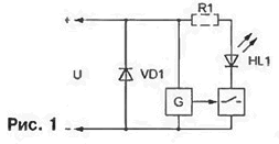
First of all let's answer the question, why is the led flashing? Inside of it, as shown in the diagram (Fig. 1), apart from the light-emitting semiconductor patterns HL1, are a pulse generator and an electronic key. Sometimes provided the quenching resistor R1, in other cases, it performs its functions the internal resistance of the key. The VD1 diode protects the device from supply voltage reverse polarity.

Incidentally, this diode is the cause of destruction of the device. Often it happens that by checking the led, a relatively powerful battery with a 9 V connect to it, confusing the polarity. As a result, the current force in hundreds mA heats the protective diode to a temperature which is dangerous not only for him itself, but also for other components of the device. Therefore, when testing the LEDs consistently it is necessary to include a resistor of 100...200 Ohms. In operation, when applied to the led voltage has correct polarity and is within the acceptable range, additional resistor 't need.
The most common "blinking" LEDs series V621, V622, V623 (firm Diverse); LTL 4213,LTL 4223, LTL 4233 (Lite On Opto); TLBG5410, TLBR5410, TLBY5410 (Temic Telefunken); L-36, L-56, L-616, L-796, L-816 (Kingbright Reinhold). In appearance they resemble ordinary ALBM, have a body diameter 3...10 mm, angle 40...1400, the color is red, orange, yellow or green. Their typical features are as follows: operating voltage is 3.5... 13, the maximum forward current is 60...70 mA, maximum power dissipation - 200 mW, frequency of outbreaks - 1,5...2,5 (sometimes up to 5 Hz), brightness - 1,3... 1000 MCD.
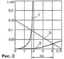
In an illuminating state of the property "blinking" led light like ordinary. Experimentally filmed the initial portion of its current-voltage characteristics it is shown in Fig. 2 (curve 1). In the intervals between flashes of the light-emitting diode circuit torn and at the same voltage the current flowing through the device, substantially less as it consumes only the internal oscillator. This condition corresponds to curve 2.

If consistent with a "blinking" led to include a resistor to drop voltage will vary in time with the flashes. With the aid of an oscilloscope you can verify that the generation continues even if you increase the resistance resistor to the value at which flashing lights are no longer visible. Held on Fig. 2 direct load (3) corresponds to a resistor of 33 ohms and supply voltage 5 V. the Difference of the voltage drops across the resistor during flash and pause AU is greater than 2 V. This is sufficient, for example, to trigger logic element.
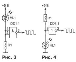
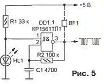
Device, scheme of which is shown in Fig. 3 and 4, by analogy with RC-generators could be called RHL-generators. Types of LEDs and logic elements the diagrams are not specified, as they were tested and worked steadily variety a combination of both. The duration of the high logic level at the output - 280...320, low - ...370 340 MS. These values slightly depend on coprogallery resistor R1 and the type of logic element. In the device according to the diagram in Fig. 3 the interval of possible resistances of the resistor R1 in kiloomah when using these chips in brackets series is 0.1... 1,8 (K155). 5,6 0,1...(K555). 0,15...30 (KR1533) or 0.15...91 (C). When approximation resistance to one of the boundary values a complete breakdown of oscillations often preceded by a "bounce" - the generation of bundles of short pulses on the fronts main. In the generator according to the scheme of Fig. 4 can work only chip structure CMOS (series C and the like), and the resistance R1 must be between 0.8...300 ohms.

In Fig. 5 shows a diagram economical generator of impulse packets containing only one NAND gate - Schmitt trigger. During the outbreak of "flashing" LEDs HL1 voltage level at the input 1 of the element DD1.1 corresponds to logic 0. In the pause between the flashes this voltage increases to a level logical 1 and starts running RC oscillator. formed elements R2, C1, DD1.1. The output can be observed packets of pulses, following with a frequency of outbreaks led. The signal can be heard by connecting to the output of the acoustic generator Converter BF1, for example, piezo oscillator SN - 1, SN - 19, SN - 22. Indicated in the diagram the component values correspond to the frequency of pulses in a pack of 2 kHz. the repetition period packs of - 500. and the duration of each of them is 230 MS. When the increase in the resistance of the resistor R1 from 620 Ohms to 150 ohms repetition period of bundles increases from 450 to 600 MS, and the frequency of their filling is reduced from 2.2 to 1.5 kHz. You can pick up such resistance (approximately 135 ohms). when which is generated sequential melodic triad. Swapping R1 and HL1, the selection of the same resistor achieve such an interesting effect, as "glissando" is a smooth change in pitch.

It should be borne in mind that all the generators here at large the values of the load resistor the brightness of the light pulses is reduced so much so that they become invisible. However, the generation of electrical impulses continues.
Author: S. Ryumik, Chernigov, Ukraine


