When establishing a radio Amateur designs, operating at frequencies above 1 GHz (e.g., in the Amateur band 23 cm), high-stability oscillator signal. It is easy to make, if there is a ham radio operator has a quartz resonator for a frequency of 27 to 50 MHz.
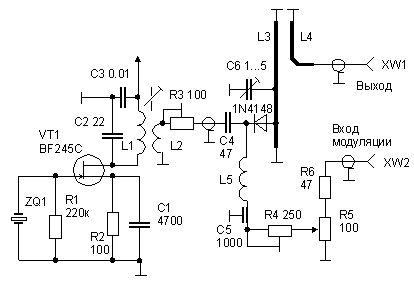
Schematic diagram of the generator shown in Fig. 1. The master oscillator is assembled on the transistor VT1, the frequency multiplier is the diode VD1. The required harmonic of the original signal (for example, 29 for Amateur band 23 cm when using the resonator for a frequency of 45 MHz) allocates circuit L3C6. The bias voltage on the diode VD1 is generated automatically. Its optimum value (maximum signal of the desired harmonics) establish a trimming resistor R4. Under the same criterion pick up (trimming resistor R3) level high-frequency voltage supplied to the multiplier to the master clock. If necessary, the output signal of the generator can be modulated. The required level of the modulating voltage set by the variable resistor R5.

Fig.1
The generator applied a conventional high-frequency diode (not designed for operation in the UHF range). If it be replaced by a Schottky diode, the output level will increase significantly.
Oscillating circuit L1C2 tune in to the frequency of the crystal. The design of the coils L1 and L2 is not critical (the ratio of numbers of turns of about 10). The inductor L5 is a frameless coil (10 turns) with a diameter of 13 mm.
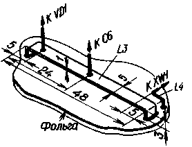
Elements VD1, C4, C5, L3 - L5 are mounted on the PCB of one-sided glass material, having all the details from the foil. Contour L3C6 is an adjustable capacitor half-wave line. Size for Amateur band 23 cm shown in Fig. 2. Make a line of copper strip, bend and solder both ends to the foil. Loop connection L4 is bent from wire with a diameter of 1 mm and have a few millimeters from the line L3.

Fig.2
Increasing the longitudinal dimensions of the line (in proportion to the reduction of the operating frequency), the described generator can be used to configure, for example, a television UHF converters.
Feed generator from a regulated source voltage 9...12 V
Transistor VT1 can be replaced by CPE, diode VD1 - KD522 or CDA.
Literature
- Prufoszillator fur microwelle.- QSP, 1988, No. 7, S. 20, 21.
-
Radio No. 3, 1989, p. 79.
Publication: N. Bolshakov, rf.atnn.ru


