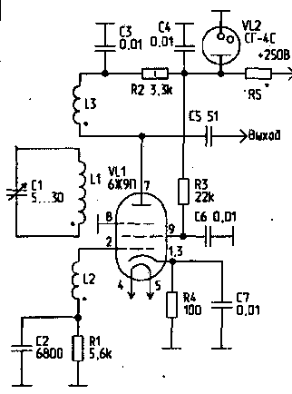
Currently there are a large number of a variety of circuits high-frequency generators with self-excitation. It is believed that they all boil down to the inductive or capacitive type. However, in 1971, I developed a scheme which is difficult to attribute to one of the two above types. In my opinion, in this case a more appropriate analogy with a physical pendulum, which is a source of energy and, in turn, part of the energy consumed to operate the source (except, of course, external losses).
Feature of the scheme is that the oscillatory LC-circuit that determines the generated frequency is not associated with the circuit conductors and any capacitors. That is, there is only inductive coupling and resonant circuit performs not only selective, but also futuredays role. The device has been experimentally tested and confirmed that it is working. There was even a patent for invention (unfortunately, then "stamped").
Still, I want to offer readers of this scheme generator.

All coils (L1...L3) is wound on one common frame-diameter 19 mm in one layer by a wire of PEL of 0.4 mm. Winding - solid round. L1 contains 20 turns; L2 - 3 turns; L3 - 8 turns. Start winding shown in the diagram. L2 and L3 are located on opposite sides of the L1. The distance between L1 and L2 is 7 mm, between L1 and L3 - 6 mm. Under these parameters the capacitance C1 overlaps the frequency range of 14 to 30 MHz.
Interestingly, the relationship between L3 and L2 in the diagram shows the inclusion and absence of circuit C1, L1 - negative, since the cascade with common cathode rotates the phase by 180°. In addition, it is the weak link (in the absence of a ferromagnetic core), since the coils are spaced far enough. Thus, generation without circuit L1, C1 is impossible (the influence of parasitic parameters are neglected).
Voltage and fields on both sides of the resonant frequency of the parallel circuit L1, C1 antiphase, therefore, making it into the gap between L2 and L3 results in terms of the balance of the phases, i.e. the total phase shift is equal to 360°. With sufficient loop gain, which is determined by the gain of the stage VL1, the magnitude of a link L3-L1, L1-L2 and losses, there comes a generation.
It is clear that with two amplification stages, each of which rotates the phase by 180°, the ends of one of the coils connection (L2 or L3) must be interchanged.
Physics of the framework are very clear compared to the schemes "trentodoc", and indeed resembles the "physical pendulum". At the same time, this scheme of work is different from some similar schemes with frequency pull. The implementation of such a generator is possible and the transistors, and the generation of easier to obtain when using the two amplifying stages.
This scheme can be used for contactless switching circuit of the subbands in the receiver. The implementation of the circuit in the form of a key can be useful for electronic locks. In addition, the scheme can be used for capacitive relay, as the links can be adjusted very easily (by changing the distance between the coils).
Author: Goncharov (RU4HG), Samara; Publication: N. Bolshakov, rf.atnn.ru


