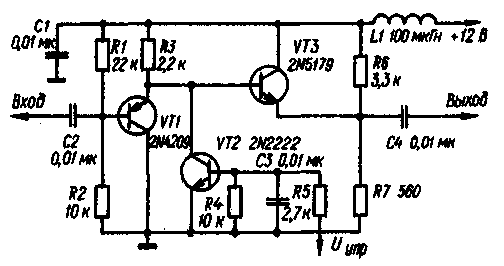
The figure shows a variant of the high-frequency switch, assembled on the transistors. He also made under the scheme of the T-attenuator, but compared with the prototype of the diodes contributes smaller losses in the open state. Moreover, it effectively functions as a buffer amp, since the transistors VT1 and VT3, through which the RF signal is connected in the circuit with a common collector.

If in the circuit of the base of the VT2 transistor to apply a control voltage of +12 V, then it will go into saturation and transistors VT1, VT3 securely closed, as their emitter transitions of the received voltage blanking polarity determined by the resistive divider R1R2 and R6R7, respectively. Besides, the saturated transistor VT2 effectively bypasses the signal chain.
To achieve good isolation transistors VT1 and VT3 must have low capacitance emitter junction and the transistor VT2 and low resistance to saturation. When using transistors indicated in the diagram (capacity VT1 emitter junction is 0.8 pF, VT3 - 1.5 pF, the resistance of saturation VT2 - 2 Ω), the calculated value of the junction between the output and the input of the switch is at a frequency of approximately 9 MHz 110 dB. This value is obtained for the idling mode output, load connection improves this parameter. For the practical implementation of such large values of the junction between the exit and entrance requires effective interstage shielding in the switch.
The output resistance of the switch about 6 Ohms. so you can use the load resistance 60...75 Ohm without noticeable attenuation of the RF signal. The current through the transistor VT3 is about 5 mA, so the maximum output the voltage at the load of 60 Ohms is limited to 260 mV, and 600 Ohm load At 2.6 V.
In the active switch can be used domestic series transistors CT (VT1), CT (VT2) and CT (VT3).
Author: Monficelli D.; Publication: N. Bolshakov, rf.atnn.ru


