


")

Circuit diagram:
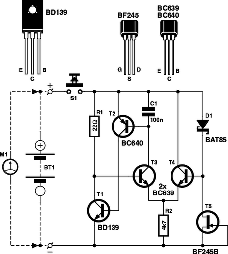
Battery Tester Circuit Diagram
Many commercial battery testers consist of nothing more than a resistor, a simple little meter and a push-button. Some manufacturers include an even simpler tester with a set of batteries, consisting of a strip of plastic with a layer of some sort of electrically conductive material that changes color when a current grows through it. If you press this strip over the battery between the positive and negative terminals, a fully charged battery will cause a more intense change in color than a partially discharged battery.
Naturally, tests of this sort do not provide especially reliable or accurate results. The idea behind the circuit described here is to load a single battery, a set of batteries connected in series, a rechargeable battery, or even a small button cell with a reasonably constant current and use a separate multimeter or voltmeter module (M1) to check the voltage. A quickly decreasing voltage indicates that the battery or batteries will have to be replaced soon. If a constant-current circuit is used for the load, the current can never too be large and there is no need to make an adjustment for the number of cells.
The constant-current circuit is specially designed to work with a voltage as low as 0.9 V. It’s quite difficult to make a circuit work at even lower voltages with normal transistors. The active constant-current element is transistor T1. The current through it is held constant by comparing the voltage across resistor R1 in its collector path with a relatively constant reference voltage across diode D1. This comparison is provided by differential amplifier T3/T4.
The voltage across diode D1 (a Schottky type) is reasonably constant by nature, but it is also stabilized by using FET T5 as a simple constant-current sink. T5 also limits the current at relatively high voltages (with several batteries in series). The constant voltage across D1 is transferred to resistor R12 by differential amplifier T1/T2, so a constant current grows through R1 from the battery or batteries being tested. R1 has a relatively low resistance, so this current is larger than the current drawn by the rest of the circuit.
The quiescent current, which incidentally is also reasonab constant, is thus negligible. The test current thus remains reasonably constant while the battery or batteries is/are being tested. The maximum battery voltage that the tester can handle is set by T5, and here it is 30 V. To ensure that T1 does not get too warm at high battery voltages, keep the test as short as possible. Use a push-button switch as a test switch so the battery being tested cannot be left under load by accident.
Source: Elektor Electronics 12-2006