


")

Circuit diagram:
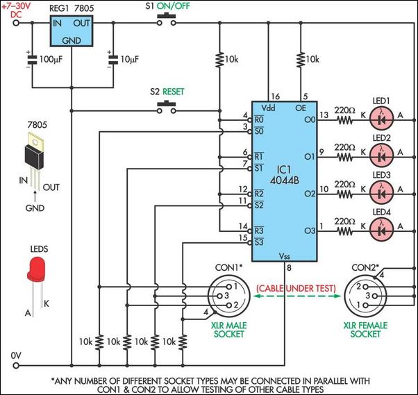 Cable Tester Circuit Diagram
A good connection for each core of the cable will mean that the relevant Set inputs of the latches (pins 3, 7, 11 & 15) will be pulled high and the appropriate LED will remain on. A broken connection in the cable will result in the relevant Set input being pulled low by the associated 10kΩ resistor and the so the LED will be off. Because the circuit latches, it is easy to pinpoint even the smallest breaks by simply flexing and twisting the cable up and down its length until one of the LEDs turns off. To test different types of cables, simply connect appropriate sockets in parallel with or in place of the XLR sockets.
Author: Ashley Dawson - Copyright: Silicon Chip Electronics