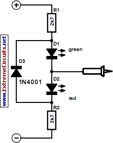
The present tester is intended primarily for testing the 24 V electrical circuits found on most pleasure craft. However, if the resistors are given different values, the circuit may, of course, be used for other voltage ranges. For 12 V, the value of the resistors should be 1.2 k?, and for 48 V, 4.7 k?. The tester should be connected to the +ve and –ve voltage rails with test clips or crocodile clips, whereupon the test probe is placed on the point to be tested. When the potential at the point is positive, the red LED lights; if it is negative, the green one does. If the supply is not connected to earth, the tester may be used as ground-leak tester. In this situation, one of the LEDs lights when the test probe touches a point at earth potential and there is a leakage.
Circuit diagram:

12/24/48 V D.C. Tester Circuit Diagram
 12/24/48 V D.C. Tester Circuit Diagram
 12/24/48 V D.C. Tester Circuit Diagram