


")

The small size of the device is achieved due to the fact that it used small details. Transistors dissipate little heat: through them when a current flows, they are fully open. The source is not critical to the circuit output.
The diagram of the power supply depicted in Fig. 1. The operating points of transistors VT1, VT2 resistors R1, R3, R5, R7 displayed on the boundary of the cutoff mode. Transistors closed, but increased conductivity plot of collector-emitter, and even a small increase in voltage on the base will lead to the discovery of transistors: i.e. reduced voltage from the secondary windings of the transformer T1 required for management. To create conditions for self-refresh, would further increase the conductivity of transistors, but to do so by further increasing the voltage on the base, because the conductivity will be different for different transistors and will change as temperature changes. Therefore, the applied resistors R2, R6 connected in parallel to the transistors.
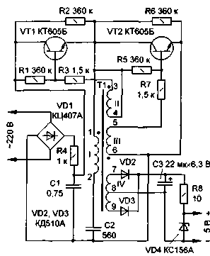
Fig.1
When you turn on the power source smoothing capacitor C1 is charged through the resistor R4, protecting diode bridge VD1 overload. The input voltage causes the output voltage to the trigger divider formed by resistors R2 and R6.This voltage is applied to the oscillation circuit from the primary winding of the transformer T1 and the capacitor C2. In the secondary winding II induced EMF pulse. The power of this pulse is sufficient for the introduction of VT1 transistor in saturation, since at the initial time, the current does not pass through it due to the inductance of the transformer T1. Then begins to flow current from the secondary winding II, holding the transistor VT1 open. The transistor VT2 during this half cycle of the oscillatory process is fully closed. It holds in this state EMF induced in the secondary winding III. After charging of the capacitor C2, the current passing through the transistor VT1, he stops and closes.
In the second half cycle of the oscillatory process in the circuit (T1, C2) current at the initial time, even when the transistors are closed, passes through the second shoulder of the trigger divider (parallel connected resistor R6 and the collector-emitter of the transistor VT2). Similarly open the transistor VT2 and then maintained in the fully open condition. After the discharge of the capacitor C2, the current through the transistor VT2 he stops and closes, Thus, the current through the transistors is only in the case when they are fully open and have a minimum resistance of the collector-emitter, so the capacity of the heat loss is small.
The high frequency oscillations straighten diodes VD2, VD3, ripple smoothing capacitor C3. The output voltage is kept constant by the Zener diode VD4. To the output of the power source can be connected load with rated current up to 40 mA. At higher current increase low frequency ripple and decreases the output voltage.
Slight heating of the transistors beyond the control of the outflow of the load, due to the fact that this device may pass through current through the transistor when the first transistor is still not fully closed, and the second began to open.
The power source can be used until the circuit output current equals 200 mA.
The transformer is made on a circular ferrite magnetic core CHG NN. The windings I, II, III, IV respectively contain 400, 30, 30, 20+20 turns of wire PELSHO of 0.07 To improve the reliability necessary to isolate the windings from one another transformer paper. The magnetic circuit can be applied with any close initial permeability and size. The capacitor C2 - km-4, or any other of the listed capacity on a nominal voltage of at least 250 V. In the absence of compact high-voltage capacitors in place of the C1 allowed to use five of capacitors connected in parallel km-5 group N volume 0.15 ICF. Although the references indicate that their rated voltage of 50 V, the majority of them can withstand constant input voltage. Their breakdown will not cause any serious consequences, since the resistor R4 will work as a preservative. Capacitor C3 - K53-16 or any small capacity and a rated voltage of not lower than indicated in the diagram. All resistors - S2-23 MLT or other small-sized. Heat sinks for transistors are not required.
The working frequency of about 100 kHz when the current consumed by the load 50 mA. More than the operating frequency of the switching transistors, the lower the inductance can be tuned circuit, and hence the smaller size of the transformer and a power source.
Correctly assembled, it should immediately earn. However, if the transistors get too hot (which means they are not fully open), choose the resistors R3, R7 and in proportion R1, R5. The output voltage may be different. To do this, change the number of windings IV and replace VD4 another Zener diode. If you need to have multiple values of the output voltage, used a series of Zener diodes connected in series.
The source can be powered devices made on digital circuits, and the other insensitive to interference apparatus. To power the radios it is not suitable because of high noise. Noise radiated into the air and brings in the network, weak, since the power source is low. The device serves as a housing battery "Krona". More detailed information about different versions of the power source, see [1-3].
In Fig. 2 is a diagram of the PCB. The Board is made of one-sided foil fiberglass or Micarta.
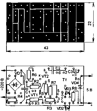
Fig.2
It can be manufactured without etching, removing the foil cutter on the lines. The transistors should install one just above the other, so that their buildings are not touching. The figures indicate the hole corresponding to the pin numbers of the transformer T1 (see Fig. 1). Pins 1 and 4 are sealed in one hole. The capacitor C1 is located above the diode bridge. Power cord fixed bracket is soldered into the Board. The transformer T1 is slipped onto the pin from the wire soldered into the Board, this pin must wear an insulating tube. Output pad soldered short thick wires to the terminals of the Zener diode. The resistors and diodes are mounted vertically.
The assembled unit is isolated by paper or film from the metal housing battery "Krone" in which it is placed.
When mounting and adjustment of the appliance observe well-known precaution network with a voltage of 220 V.
Literature
Author: Solonin, Konotop, Sumy region, Ukraine; Publication: N. Bolshakov, rf.atnn.ru