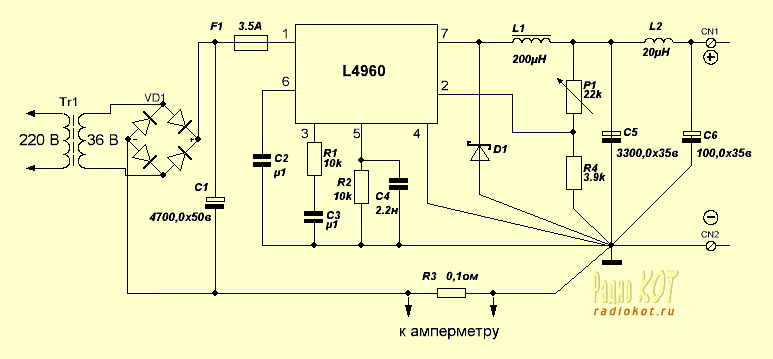
Modern circuitry and chip manufacturers cool make life easier for the designer - for example, when creating an supply. We will demonstrate it on the chip L4960.According to the plant documentation, it is possible to produce a regulated power supply with an output voltage of 5.1...40 V, with load current of 2.5 A, built-in current protection and overheating, up to 90% efficiency. Power dissipation with heat sink - 15 watt, case HEPTAWATT, frequency conversion 50..150 kHz.

The figure shows the scheme of inclusion, mainly the corresponding recommended.
Explain the purpose and characteristics used items. Transformer - power not less than 80 watts, an output voltage of 36 volts and a current of 3 amps. Capacitors C1,C5,C6- conventional electrolytic. Capacitor C2 provides a "soft" inclusion chip, and can be a capacity of up to 2 µf. The capacitors C3 and C4 are asking the operating frequency and frequency compensation built-in generator, type- film. The diode D1 is best Schottky, a frequency of 100 kHz and a current of at least 3 A. Resistors R1,R2,R4 - ordinary power of 0.25 W,R3-wire, resistance of 0.1 Ohm 1% 1W, serves as a shunt for the ammeter (I would like to see the distinguished Author and readers that modern measuring head amp and voltmeters do not need external the bypass, because you have an internal shunt. Approx. Cat.);can replace the jumper if you do not want to measure the current. Resistor R1- multi-turn, serves for fine adjustment of the output voltage; replace the two serial - to coarse and precise installation voltage.
The parameters of the inductor L1 is the inductance of 150..300 microhenry. When the inductance of 150 μh maximum output current will be equal to 2 And, when inductance 300 µh - 3. When modeling scheme was checked by different chokes different inductance, on different cores, different wound wire. The best results are obtained on a ferrite ring wire with a diameter of 1 mm. unfortunately, the chokes were all factory winding with unknown magnetic permeability and number of turns. It was possible to measure only the inductance and impedance of the windings. Chip the ability to dissipate power up to 15 watts, and therefore for adjustable stabilizer need to install it on the appropriate radiator area not less than 200KV.cm. It is desirable to provide a radiator and a rectifier bridge VD1. L2 and C6 - optional elements, serve to eliminate switching power surges.
Characteristics of the resulting stabilizer
output voltage 5...32 volts;
the maximum current is 2.5 amps, Overdrive decreases the output voltage, self-healing occurs when the load increase of 20..30%;
high frequency ripple of the output voltage less than 10 mV and less than the variation in the output voltage when the input voltage.
The stabilizer is assembled in the housing from a former computer PSU dimensions HH,5 see as a digital indicator used the finished module based on CPW.You can use the module as described in the article "digital display". Figure prints Board is contained in the format SPL4, in the form suitable for printing on printer without a "mirror" of the turn.
Publication: www.radiokot.ru, www.cxem.net


