The article describes a very simple switching power supply. Its simplicity due to the use of "electronic transformer" - serial products, designed to power the halogen lamps.
To power modern electronic equipment is becoming more widely used find the impulse source, in which the voltage is converted to high frequency. This allows, as we know, significantly reduce the size and weight such power supplies compared to linear.
However, novice hobbyists at independent manufacture of a pulse power supplies causes the greatest difficulty establishing, during which often fail expensive high-voltage transistors. Yes and supply the voltage in the primary circuits are galvanically connected to the network, quite high - about 300 In that, first, places high demands on winding the isolation Converter transformer, and secondly, makes the establishment of such block a dangerous activity.
Quite simply, this problem can be solved if you use a ready-made device - "electronic transformer". Such devices went on sale a few years ago in specialized stores selling professional electrical and commercial equipment.
"Electronic transformers" designed to power 12 volt halogen the backlight of the display cases. They are supplied directly from the mains voltage of 220 V, frequency 50 Hz, and the output - pulse AC high-frequency amplitude of 12 V.
In the described device is equipped with a transformer rated at 105 watts, however, there more powerful models. Depending on the country of manufacture and trading organization the price of this product ranges from 250 to 350 rubles.
In fact, such a transformer is a very compact pulsed the voltage Converter. Conversion frequency (depending on model) is from 50 to 80 kHz.
For practical use in the power supply "electronic transformer" requires no modifications. You only need to make a surge protector, matching transformer, rectifier and output filter.
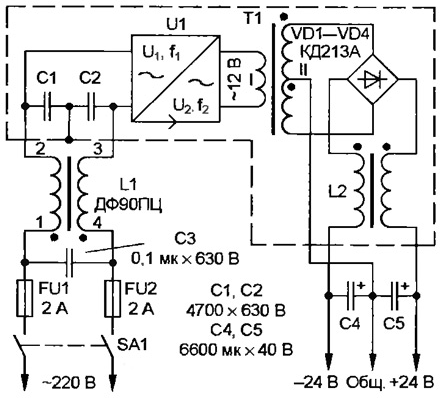
The figure shows the circuit of a power source on the basis of similar products. It the device for two years works in conjunction with a stereo amplifier with an output of 2x20 watts. Its output voltage under load 100 mA at nominal line voltage of 220 V - ±25 V. If the load current increases to 2.2 A, the output voltage decreases to ±20 V.

The supply voltage through the switch SA1 and the fuses FU1 and FU2 comes the filter L1C1 - C3, protecting the network from interference pulse Converter. The average switch point of the capacitors C1 and C2 connected to the shielding casing the power supply unit. It should be particularly noted that the casing must be isolated from common wire and the metal chassis of the powered device (load).
Next, the supply voltage is input to an "electronic transformer" U1 output terminals of which (labeled 12 In) low voltage serves to matching transformer T1. The AC voltage from the secondary winding of transformer diode bridge rectifies VD1-VD4 and filter smooths L2C4C5.
The inductor L1 used ready DPPC from TVs ZUSTST.
The transformer T1 is produced. The number of turns of the secondary winding depends on the output voltage of the power supply. The transformer is made on an annular magnetic core Chg ferrite MNM. The primary winding has 10 turns of wire sew-2 to 1.2. The secondary winding (output voltage of ±24 V) wound folded in half wire sew-2 to 0.8. It contains 22 of the coil. Connecting the end of the first Polubotko with the beginning of the second, get the average point of the secondary the winding.
The inductor L2 is also homemade. It is wound the same as the transformer, a ferrite ring CHH MNM wire sew-2 to 0.8. Both windings contain 20 turns.
Rectifier diodes should be placed on the heat sink area of not less than 50 cm2. Moreover, the diodes whose anodes are connected to the negative output of the bridge should isolate from heat sink mica spacers, and the heat from the casing the power supply unit.
Smoothing capacitors C4 and C5 are composed of three parallel connected C50-46 with a capacity of 2200 UF each.
The shielding casing can be made of thin sheet brass or tin-plated tin. In it is necessary to provide holes for cooling.
Details of the power supply unit is placed on the Board of insulating material and connected lengths of insulated bonding wire. The design should to completely eliminate the possibility of touching the conductors and parts the device is connected to the input "electronic transformer", which is are the AC line voltage.
Correctly assembled power unit begins to work immediately and in establishing not needs. While checking the output of each of the shoulder should be connected resistors the resistance of 240 Ohms with a power dissipation of at least 3 watts. No load block include not recommended.
If the powered device comprises a highly sensitive circuit (such as microphone amplifiers), then the smoothing capacitors C4 and C5 useful shall be shorted ceramic load capacitance of 0.33 μf at nominal the voltage of at least 63 In (you can include multiple capacitors in parallel).
Author: Andrei Sharonov, Chita


