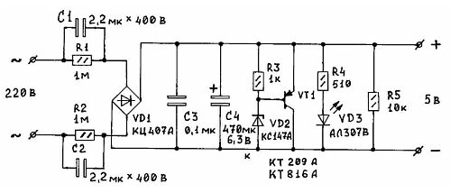
The proposed power supply is very simple, even primitive scheme. Deprived so heavy and bulky items, like a transformer, and does not contain any scarce elements. I designed it to power a portable receiver. Since the unit is small in size, I was able to put him into the battery the receiver box.

The disadvantages of this scheme, many can be attributed to the lack of galvanic isolation from the mains, but for all the good you have to pay. Another the disadvantage could be considered an opportunity to get hands on the phase wire, however, such conclusions should not act hastily. Imagine a situation when you relate the phase wires. If you are not “grounded", i.e. do not run through his the body current, you can hold on to this same phase as Your heart desires.
Hence the conclusion is clear - the importance is not so much the fact touch the phase wires much the value of the current passing through your body. For this reason the quenching capacitors installed in both power lines power. Now how do not plug the power plug into the mains socket - a minimum of one the capacitor will be between the phase and the rest of the device, and you may a little “pull" (or a bit more than a little).
It all depends on your resistance and resistance of the capacitor AC current. But still resist the temptation of such experiments. The amount of resistance can be calculated by the formula:
Rc = 1/2πFC,
where RC is the resistance of the capacitor in ohms; F - frequency, Hz; C - capacitance capacitor, F. resistance of the two parallel-connected resistors:
R = R1R2/ (R1 + R2).
Knowing these formulas, we can apply Ohm's law to calculate the required the ballast resistance in the circuit to provide the required current to the load. Determine the capacitance of the capacitor. In the simplest case, if we multiply the obtained capacity for two C1 = C2 = 2C. according to the scheme in the figure. Resistors R1, R2 designed to discharge the capacitors, they shunt. Diode bridge VD1 expect a corresponding current in the circuit. Its maximum operating voltage is determined by the voltage that provides the Zener diode in the load. Accordingly, we choose a suitable voltage and capacity of the capacitor C4.
Elements R3, VD2, VT1 constitute a powerful analogue of the Zener diode. The maximum current and power dissipation of this Zener diode is determined by the maximum current and the power dissipation of VT1. For this transistor may require a heat sink. But in any case, the maximum current of this transistor must not be less than the current load.
Elements R4, VD3 form a chain of indication of the voltage at the load. When small load currents in the calculations must take into account the current consumption of this chain. In case of absence of necessity in the chain - just eliminate it. Resistor R5 operates as a load, loading down the power a small current than stabilizes its work.
Setup and components. The quenching capacitors C1 and C2 - type KBG or similar, they are the most reliable. You can also apply and K73-17. Best option - when the maximum voltage is 400 V, 250 although it is possible To, so as they are connected in series. The output voltage depends on three factors: 1) the resistance of the quenching capacitors AC; 2) from the actual current load if it exceeds the calculated value; 3) from the Zener diode, more precisely, from its voltage stabilization. Choose what you need. Correctly calculated and collected from the healthy elements of the unit requires no configuration. Finally, I note that collecting this power supply and measure ripple on it load, I was pleasantly surprised by the almost complete absence of ripple and noise on it output.
Author: Efimenko, V. B., Kiev


