


")

LED1 indicates that the battery is connected and that power is available. The 555 timer IC is configured as an astable oscillator running at approximately 100kHz. It feeds a diode pump (D1 & D2) to generate adequate gate voltage for Mosfet Q3, enabling it to turn on with very little on resistance (typically 14 milliohms). With the Mosfet turned on, current flows from the charger's positive terminal so that charging can proceed. The battery voltage is monitored by 10kO pot VR1.
Circuit diagram:
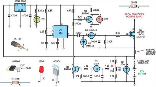
Battery Charger Regulator Circuit Diagram
When the wiper voltage exceeds the conduction voltage of zener diode ZD1, transistor Q1 turns on and pulls pin 4 (reset) low to switch off the 555 and remove gate drive to the Mosfet. This process is progressive so that the cycle rapidly repeats itself as the battery charges. Eventually, a point is reached when the battery approaches its charged condition and the cycle slows right down. Transistor Q2 and LED2 function as a cycle indicator. When the battery is under charge, LED2 appears to be constantly on. When the battery is fully charged, LED2 briefly flicks off (charging) and returns to the on state (not charging) for a longer period.
Author: Paul Walsh