


")

Circuit diagram:
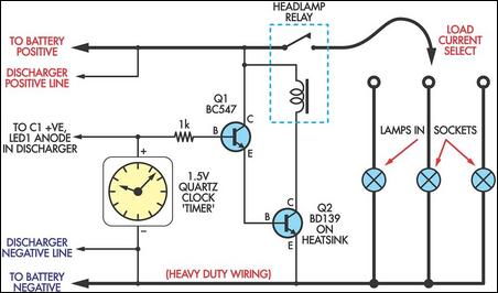 High-Current Battery Discharger Circuit Diagram
With 12V selected, the prototype unit stops the discharge at 11.4V which corresponds to a cell voltage of 1.9V (this is a pretty good indication of a discharged 12V battery). The loads consist of three automotive lamps, selected to provide discharge rates to suit the battery being tested. These lamps should be fitted to sockets, so that they can be easily swapped for other lamps with different wattages, if required. That way, the discharge current can be varied simply by changing the lamp wattage. By the way, this circuit will also work with 6V batteries, provided the relay holds in. This gives an "end-point" voltage of about 5.7-5.8V.
Author: Reg Carter - Copyright: Silicon Chip Electronics