


")

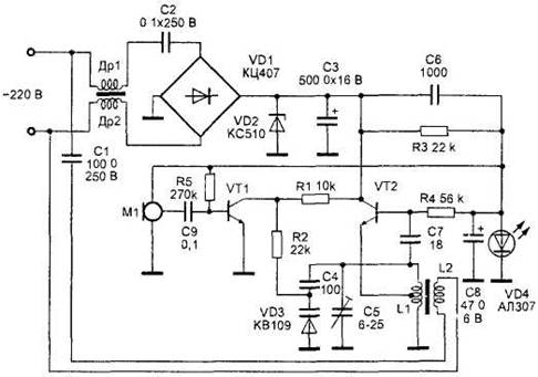
Figure 17. A radio transmitter FM frequency range 1-30 MHz.
The power supply device is assembled in a transformerless circuit. The mains voltage of 220 V is supplied to the inductors DR1, dr2 do and a quenching capacitor C2, which diminishes the excess voltage. The AC voltage is rectified by a bridge VD1, the load of which is a Zener diode VD2 type X. Ripple voltage smoothing capacitor C3. The modulating amplifier is made on the VT1 transistor KT315 type. The audio signal is supplied to the base of this transistor with electret microphone with amplifier M1 type FEM-3 or M1-B2 "Pine". The amplified audio frequency voltage across the resistor R2 is supplied to the varicap VD3 type SW109А, capacitance measurement which allows to perform frequency modulation. The master oscillator is made according to the scheme of inductive treatacne on the VT2 transistor KT315 type. The oscillator frequency is determined by the elements of the oscillating circuit L1, C5, C4, VD3. Feedback is via a capacitor C7. Modes of transistors VT1 and VT2 DC are regulated by the resistors R5 and R4, respectively. Bias voltage of the transistors VT1 and VT2 are formed by these resistors and the parametric stabilizer made on the resistor R3, diode VD4 type AL307 and the capacitor C8. This is a higher frequency stability than the usual inclusion. The voltage of high frequency, frequency modulated sound signal from the coil L2 connection enters the network 220 through a coupling capacitor C1. Capacitor C1 reduces the effect of voltage on an oscillator. Chokes DR1 and dr2 do exclude the penetration of high frequency voltage on the supply lines. Chokes DR1 and dr2 do wound on ferrite rods and comprise 100 turns of wire sew 0.1 mm each. Coils L1 and L2 wound on the frame with a diameter of 5 mm with a trimpot core. For the range of 27 MHz coil L1 has 10 turns with tap from the middle of the wound wire sew 0.3 mm. of the Coil L2 has 2 turns of the same wire. Capacitors C1 and C2 must be rated for the working voltage is not lower than 250 V. Diode Assembly CD can be replaced by four diodes CD, CD. Instead of the Zener diode VD2 can be used with any other voltage stabilization 8-12 V. Led VD4 type AL307 can be replaced with any led or two or three silicon diode included in the forward direction. When you use certified parts and proper installation, tuning is the tuning frequency of the master oscillator by a capacitor C5.