


")

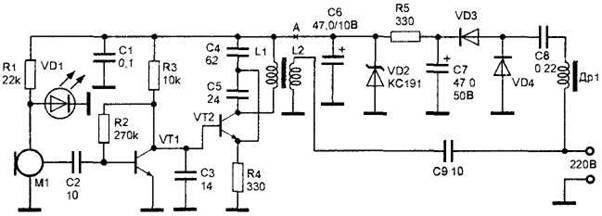
Figure 16. Radio with AM in the frequency range from 27 to 30 MHz.
The master oscillator is assembled on the VT2 transistor KT315 type according to the traditional scheme. To power the microphone M1 is applied parametric voltage regulator, assembled on the resistor R1 and diode VD1 included in the forward direction at the anode of which is supported voltage 1.2-1.4 V. On the VT1 transistor KT315 type assembled USC, the signal modulates the amplitude of an oscillator. The DC voltage at the collector of the transistor VT1 is the voltage of mixing for the transistor VT2. Modulated RF signal from the coil L2 connection through the capacitor C9 is fed into the grid. In this case, the wires act as an antenna. The power source is assembled by a transformerless circuit. Choke DR1 prevents the penetration of HF oscillations in the power source. On the reactive resistance of the capacitor C8 is extinguished over mains voltage. Unlike the resistor, the capacitor is not heated and does not emit heat, which is beneficial to the operation mode of the device. The rectifier is assembled on the diodes VD3, VD4. Capacitor C7 smoothes the rectified voltage ripple. Further, the voltage across the parametric stabilizer, assembled on the resistor R5 and the Zener diode VD2, is supplied for powering the radio microphone.
The capacitor C6 reduces the pulsation of the rectified voltage. This power supply provides stable operation wireless microphones with changes in the mains voltage in the range from 80 to 260 V.
The microphone M1 is any compact condenser microphone with built-in amplifier (FEM-C, M1-B, and "Pine", etc.). Capacitors C8 and C9 must be designed for a working voltage of at least 250 V. the Inductor DR1 type DPM-0.1 par value 50-90 µh. Choke DR1 can be made independently. It contains 100 to 150 turns of wire sew 0.1 mm on a standard ferrite core with a diameter of 2.8 mm and a length of 14 mm (the length of the core can be reduced in 2 times). Coils L1 and L2 wound on a standard ferrite rods with a diameter of 2.8 mm and a length of 14 mm wire sew 0,23. Coil L1 - 14 turns, L2 - 3 turns on top of L1. The VT2 transistor can be replaced by KT3102 go KT368. Led VD1 - for every led. Diodes VD3, VD4 are replaced by CD or other, for a voltage not lower than 300 V. the Capacitors C6 and C7 can be larger capacity and higher working voltage, they should have minimal leakage. The Zener diode VD1 can be replaced by any Zener diode with voltage stabilization 8-12 V.
Scheme of the network adapter is presented in figure 16.
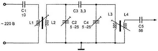
Figure 16-a. Scheme of the network adapter.
The capacitor C1 prevents the penetration of mains voltage in the coil L1 and the input of the receiver used.
Coils L2, L3, L4 and capacitors C2, C3, C4 form a double-circuit FSS. With the coil L4 and the filtered signal is input to the receiver. Coils L1, L2, L3, L4 are wound on frames from SW coils of portable radios. The coil L1 has 2 turns; L2 - 14 turns; L3 - 14 turns; L4 -5 turns. All coils are wound wire sew 0,23. Capacitor C1 is a voltage lower than 250 V, the capacitors C2 and C4-rigged. Your device should start with checking the voltage. You need to make the gap at point A. the voltage on the capacitor C6 should be 9 V. If the voltage differs from that specified, check the serviceability of the elements of the power supply unit DR1, C8, VD3, VD4, C7, R5, VD2, C6. With the reliability of the power supply to restore the connection at point a and the selection of resistor R2 to set the voltage on the base of the transistor VT2 equal to 3.5 V. Further configuration is to install the carrier frequency tuning loop by moving the core of the coils L1, L2. Schemes need to fill in with epoxy, pre-shielding the microphone. Configure the adapter is reduced to a set of contours L2, C2 and L3, C4 to the transmitter frequency.
ATTENTION! When you set up and operate devices with a transformerless power supply from the AC must comply with the rules and security measures since the elements of the devices are under a voltage of 220 V.