If a person has become worse to hear, it's hard to use a phone apparatus. Of course, you can purchase a special device for the hearing impaired, but it costs a lot, and not everywhere is on sale. Much easier to add to the existing apparatus of a simple amplifier and the problem is solved.
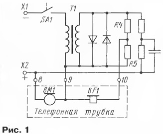
In Fig. 1 shows a fragment of the schema of the "Tulip" production pnrm., trapped by the author.

To the terminals X1 and x2 connects the telephone line (for example, through self-PBX or communication devices) so that the clips were specified voltage polarity (this is important for connected to the amplifier apparatus). It is not necessary to measure with a voltmeter the voltage at the terminals, it is enough to measure it on findings 8 and 9, suitable to the handset. Typically, when off-hook (and, hence, the closed contacts of switch SA1) and coal microphone WM it can be measurements of the author, a 2.7...4.5 V, but in some other phones will increase to 8... 16 V. This voltage and will supply for the amplifier. Depending on you should choose a transistor amplifier circuit.
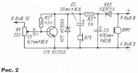
The amplifier circuit shown in Fig. 2.

It is easy to see that the phone BF1 tube connected to the output of the amplification stage, and to the conclusion of the 10 who had gone up earlier to the phone connected variable resistor R1, which adjust the sound volume in conversation with the caller.
From the engine, variable resistor signal is supplied through the coupling capacitor C1 for amplifying cascade, performed on the transistor VT1. The offset on the basis of transistor is set by resistor R2, load cascade DC is the resistor R3. Phone BF1 tube connected to the collector of transistor through the coupling capacitor C2. The power supply for the cascade is removed from capacitor C3, which receives not only the DC voltage falling on the microphone, but rectified by the diode VD2 alternating voltage appearing on the microphone during a conversation. In addition, thanks to the chain VD2C3 eliminated the self-excitation of the device due to the acoustic coupling between the microphone and a telephone.
The Zener diode VD1 in this case acts as a limiter voltage possible jump of the supply voltage, for example, in the case shutdown (due to poor contact) microphone or its failure.
The resistor R1 may be of any type, its resistance should be approximately the same the resistance of the telephone handset so as not to disturb the operation mode of the apparatus. Capacitors - any oxide for a rated voltage not lower than a specified the schema. The Zener diode is chosen with a minimum voltage stabilization above the maximum possible supply voltage by about 10 %.
When establishing the amplifier resistor R2 are selected such that the voltage between the collector and emitter of the transistor was equal to about half the supply. The handset must be lifted.
At the completion of a telephone current consumption from line almost not increased.
Author: B. Sadowski, Chelyabinsk


