Currently, the markets and the shops appeared in the sale of "talking" clock in variety of designs - wrist and table. They can be used as an answering machine, telling time, on departmental and PBX.
To install the answering machine will need a separate telephone line to be used only for the purpose of obtaining information about the current time. The subscriber is calling the number associated with this line, and hears a voice message of "talking" hours.

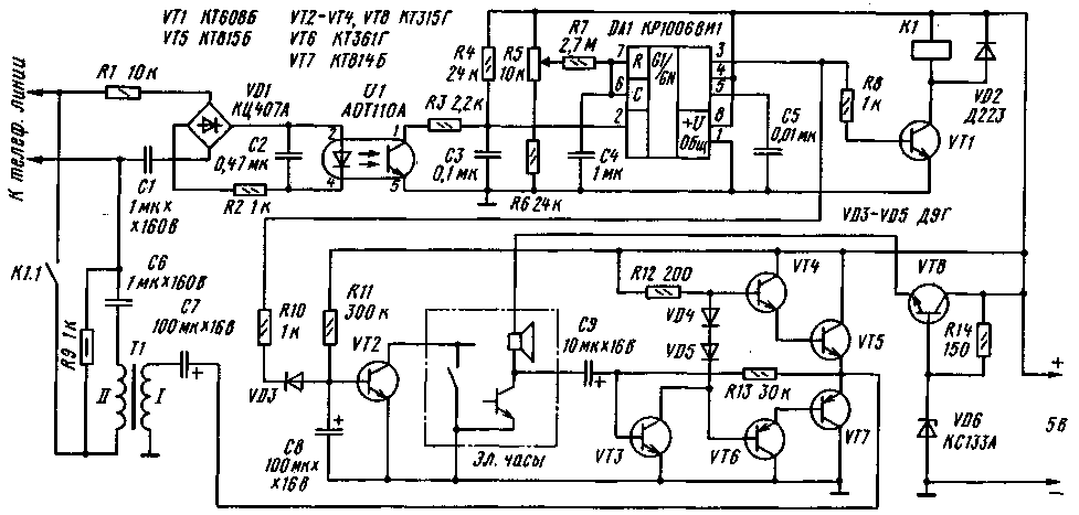
Diagram of the device shown in the figure. Calling signal from the telephone line is supplied to the diode bridge VD1. Through the led of the optocoupler U1 current begins to flow. The optocouplers transistor opens and there is a discharge of the capacitor NW through the resistor R3. When the first low level (below 2/3 of the supply voltage) at pin 2 of chip OA starts the timer and its output (pin 3) there is a high level [1]. Transistor VT1 opens and activates the relay K1. The Contacts K1.1 is connected to line resistor R9, and the alert is terminated. The timer DA1 is enabled in single-shot mode. The pulse duration determines the chain R5R6R7C4. This duration should be selected so as to leave a pause between the end of a voice message and disconnecting the resistor R9 from the line.
With the appearance of high level timer output diode VD3 closes and starts the charging of capacitor C8 through resistor R11. Chain R11C8 sets the pause before "response" hours. Then opens the transistor VT2 and will shunt the button "reply" on the clock. With a clock output audio signal fed to the amplifier, which is assembled on the transistors VT3 - VT7. He is described in [2]. Through the transformer T1, the output signal of the amplifier is fed into the telephone line.
When a pulse generated by the single-shot is over, the output DA1 will occur is low. As a result, the transistors VT1 and VT2 will be closed. The Contacts K1.1 disconnect the resistor R9, and the unit will return to the original mode. The stabilizer elements R14, VD6, VT8 generates the supply voltage for the clock.
Relay K1 - RASA, passport RS4.569.724. Transformer T1 is used from telephone set TA-68. Optocoupler U1 can be replaced by AOTA.
The dynamic head of the electronic "talking" clock need to be disabled, and instead connect the resistor 51 Ohm.
Literature
Author: A. Kharchenko, Rybinsk, Yaroslavl region; Publication: N. Bolshakov, rf.atnn.ru


