


")

Firm MATSUSHITA recent years manufactures VCRs and videoplayer with LSM Z-type is equipped with a diagnostic system. In the published article here author tells about LSM, service modes, and makes recommendations for repair of these devices.
Apparatus company MATSUSHITA with the brand name PANASONIC is well-known in Russia and other countries of the former Soviet Union. Meets the equipment of this company and with trading brands NATIONAL, QUASAR. Recently we also began to bring stereo VCRs from Europe (pre-owned) with the "stuffing" from MATSUSHITA under the brand names BLAUPUNKT, GRUNDIG, etc.
Until the mid 90-ies in the apparatus used PANASONIC tape drive mechanism (LSM) type G (model G-REV, G-II). From the middle decades of the models in SUPER DRIVE the firm began using mainly the mechanism of K. It is used in modern VCRs with S-VHS of the highest class, for example, NV-HS960. At the end of the 20th century, there was a mechanism Z, which is simple and relatively a small number of used parts. These LSM complement all modern model video recorders and videoplayer of the company, including the very popular stereo VCR player NV-FJ8AM, 2003 - modification NV-FJ8AM Inc.
Obviously, the mechanism of Z represents the latest development of the company, designed for VCR analog formats. Recently the Director the company MATSUSHITA ELECTRIC INDUSTRIAL Fumio of Otsubo said the following: "We put an end to the VHS market, which we have developed, and are now doing first step towards the creation of a market for DVD recorders". The firm will gradually to curtail production of VCRs and move on to the production of DVD recorders. Their ads have already appeared on our television.
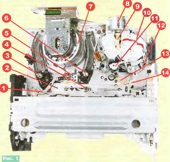
The appearance of the mechanism of Z PANASONIC VCRs shown in Fig. 1 and 2 example of LSM VCR PANASONIC - NV-HD640EE. Numerals in Fig. 1 marked (in parentheses nomenclatural designation): 1 - the node controller of tension tape (VXL2793); 2 - strap software (VML3166); 3 - node feed the rack rail (VXA6040); 4 - prism Central led (VMD2738); 5 -- gear rack actuator nodes refills tape (VXL2447); 6 - node reception the rack rail (VXA5854); 7 - urh; 8 - node engine fueling (VEM0604); 9 - "worm" of the engine fuelling; 10 - gear software (VDG1220); 11 - the lever pressure roller (VXL2785); 12 - the lever of a drive of Reiki magazine download (VML3165); 13 - the lever the rack rail R5 (VXL2677); 14 - lever actuator software strap (VML3167).
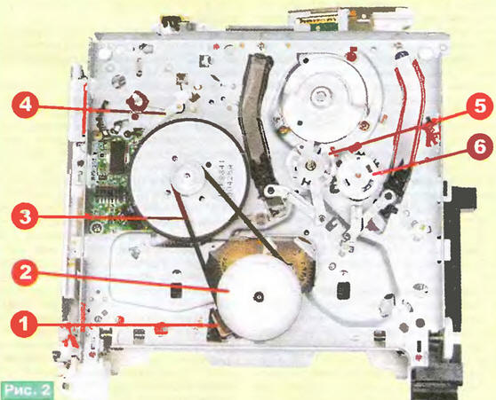
Numerals in Fig. 2 denote: 1 - the lever of change of mode IN (VML3177); 2 - node for winding and rewinding (VXP1850); 3 - belt (VDV0372); 4 - brake lever (VXZ0430); 5 - drive unit reception (VXL2670); 6 - feed drive unit rack (VXL2672).
Recorders mechanism Z is equipped with a self-diagnostic system fault, allowing to detect some faulty nodes or devices. When a fault occurs, the system provides an indication of its code on the display in the form of Latin letters and two digits. Fault codes displayed by the system self-test, presented in table. 1, which is taken from the service manuals characteristic of translation on Russian language.
It should be noted that the number of possible faults that actually occur on practice, of course, and much more practical benefit from such a system when the repair is relatively small. In addition, the recommendations shown in the table, to use is quite difficult because it is not always clear how to perform them. It is therefore advisable to specify and complement the example VCRs models NV-SD570, NV-HD670 and NV-FJ620 (model 2001, 2002 issue).
Code U10. The humidity sensor is installed in all models of VCRs. In those phones where it is, when you receive the code U10 measure the voltage across the corresponding output of the BIS management system, for example, at pin 1 microprocessor MN675567VRWD. This LSI is used in PANASONIC VCRs - NV-SD570AM/EU, PANASONIC - HD670BD, however, the humidity sensor is placed only in model NV-HD670BD. In 570 models pin 1 of the microprocessor is connected to a common wire. If replacement of a faulty humidity sensor the corresponding output of the microprocessor can also be connected with the common wire.
Code U11. In addition to this table, the causes of such a code can be damage or wear on the video heads, the violation of the connector pins connecting pre-amplifier with the main Board of the device, malfunction of the preamp and channel of the image.
Code H01. The first thing is to check the presence of voltage 14 V UNREG (+14) at the output of the power source. For 570 and 670-x models is the contact 15 of the connector R. You also need to verify the integrity of the throttle L1121 and diode D1121 in the power source (model NV-FJ620 position L1250, D1250, D1251). Reasons failure of drive motors Rhu often malfunction of the Hall sensors. Their items not in the specifications of the service manuals. The firm recommends replace the stator of the engine (engine type - VEK8840). However, suitable the sensors are on sale at radio.
Often failure occurs due to contact failure connecting the connectors and the appearance of microcracks in the printed conductors, so you must check ("check") all circuit connecting the motor drum with chip electric AN3811NK (IC2501). Waivers are not the chips themselves excluded, however, in practice this occurs very rarely, chip electric Rhu company MATSUSHITA have high reliability.
Codes H02 AP, F05. Rasprava tape, i.e. podmicivanje it in the cassette, occurs when turn off the VCR press POWER. And in the process of raspravki rack rails are half way to the start position (it is shown in Fig. 1), then returning to the position of the raspravki (tape covers Rhu), then the device returns to the standby mode. When implementing mode EJECT process raspravki is brought to the end (rack rails occupy position, as in Fig. 1), followed by ejection of the cassette.
The absence of winding of the tape feed polituchnica during raspravki may have as "electrical" and "mechanical" reasons (symptom - the ejection of the cassette with an untucked loop tape). To "electrical" refers a malfunction in the electric drive system of the leading engine systems automatic regulation and control of the VCR, to the "mechanical" failure and wear parts and components of LSM, as well as incorrect Assembly of the mechanism in the repair. Since VHS mechanism Z no access to the lower part in the time, it is impossible to see what is happening during the raspravki tape.
To check the rotation of a driving motor in an indirect way, by connecting oscilloscope to the circuit of the speed sensor of the engine (usually pin 4 of connector R or R in the model NV-FJ620). The amplitude of the sinusoidal signal coming from this sensor - units of millivolts, so it may be easier to observe enhanced to 0.6 In the sensor signal on the output 84 of the microprocessor MN675567VRWD (reference point TL2015 in models 570 and 670-x) or at pin 86 of the microprocessor in C2CBHF000199 machines NV-FJ620 (same reference point).
The most likely "mechanical" reasons for the lack of winding of the tape can call slippage of the belt drive 3 and the wear of the winding unit 2 (Fig. 2). Proposed in the table check the availability of pulses from the rotation sensors podkastov in this case has no practical meaning, as if the tape is not podmahivat, pulses, obviously, and never will.
Codes F03, F04, F06. A control unit engine download is included chip leading electric motor AN3844SB located on the Board its stator. Communication engine download from the main Board is provided via Vrubel two-pin connector R (model NV-FJ620 - R), circuit LOAD METER(+), LOAD M(-), the contacts 9 and 8 of the connector R leading engine (620-th model connector R) and outputs 19, 21 of the chip of the drive AN3844SB. Control signals for this chip are circuits LOAD) and unloading (UNLOAD) conclusions 70 and 72 of the microprocessor MN675567VRWD (pin 87 and 86 of the processor C2CBHF000199). Modes of loading and unloading are realized at a high level (+5 V) in the respective circuits.
To check the phasing mechanism, the desired service manual (experienced the master, of course, cost. The partition Assembly is rather large and playing it in the journal is not possible. Switch modes, in other words - software switch, is mounted on the main Board and check it problematic. You only have to clean the contacts a common manner.
Code F09. To check the microprocessor in practice is also not possible. Tire exchange of information with the timer chip is composed of three chains connecting conclusions 63 (TALK TEST), 64 (TEST LSN), 65 (CLK TEST) microprocessor MN675567VRWD findings 13, 14, 15 BIS M355000FP timer. Pulse amplitude in all circuits about 5 V.
When the indication of the letters N F or the recorder is switched to standby mode. When you power on again, the display returns to the default mode. Code failure (two digits) EEPROM memorizes and stores even when disconnected power. It can be displayed on the display in the service mode. If you experience subsequent faults in memory will be listed code the last of them. For erase the code you need to simultaneously press the buttons (FF, REW, EJECT and to hold them for 5 seconds.
For a more accurate location of a fault in the PANASONIC VCRs there is a service mode as in the models with the mechanism, and in models with mechanism Z (videoplayer this is not the case, as there is no display on the front panels). The technology works in the service modes for different models of VCRs in General not the same. However, the ways of entering in service mode and methods of work with it are the same for whole lines models of VCRs, and they can fully or partially coincide at devices with mechanisms and To Z.
Sign in service mode most models occurs while pressing FF, EJECT and hold them for 5 seconds In some devices you need to simultaneously press the buttons (FF, REW, EJECT. In addition, in most models with the mechanism To the service mode you can enter in the control circuit points TP GND TP SERV.
Consider one of the options in the service mode manual maintenance of recorders mechanism Z. After entering mode the display shows service information: hours in the discharge room service mode, in the discharge of the minutes - the number of the service data, in the discharge of seconds - the service code. The latter often corresponds to one of codes faults specified in table. 1: H01 - 01, H02 AP - 02, F03 - 03, F04 - 04, F05 - 05, F06 - 06, F09 - 09. In table. 2 shows the service data and the modes with the review, by which we can judge about the location of faulty components (table from the service manuals).
(click to enlarge)
Sequential selection of the service modes with the push of a button EJECT simultaneously press and hold the FF button.
In the service mode 1 check the operation of the phototransistors and Central infrared led cassette. Code 00 indicates the Central fault of the led or its power supply circuit. The voltage the led D6001 in 570 x 670 models is supplied through a resistor R6012. This same code is indicated and the fault of both phototransistors. Code 01 indicates in the absence of an identification signal from the left phototransistor, and code 02 - right. Since the phototransistor is connected directly to the conclusions microprocessor, the presence of these codes indicates an error themselves phototransistors, although in practice the repair there are cases when the cause the fault is severe contamination of the surfaces of the led and, though less frequently,phototransistors. Code 03 indicates a healthy system identification of the presence of the cassette.
Service mode 2 is used for checking the operation of the mechanism in different modes, listed in table. 2. They need no comment, except for the modes STOP. They are implemented in the standby mode with a full cassette and tape. Operating modes the STOP and PAUSE are obtained without removal of the clip from the tone of the shaft.
In service mode 3 check the software switch. During the change of regimes the work of LSM observe the change of the codes is not required. The serviceability of the software switch and the correct Assembly (i.e., different phasing) mechanism must be indicated by the code 00 after each operation.
Service mode 4 provides verification of the control buttons on the front panel apparatus and the remote control. Service data appears when entering commands the buttons on the microprocessor. The number of codes is rather large, but to list them values are unlikely to be appropriate. The correctness of the commands for sure changing the values of the codes by pressing buttons.
In the service mode 5 check the drive shaft. Some the problems mentioned above, as well as about the problems with electric Rhu identified in the service mode 6.
The order of actions in the service mode applies to a large number models of VCRs with mechanisms To Z and released approximately In 1998. later models with the mechanism of the Z-order of operation in the service mode may be different. Briefly describe it on the example of model NV-HD640EE (1999-2001 gg.).
To enter service mode need to simultaneously keep pressing the FF button, EJECT more than 5, and to switch modes as above. In the service mode 1 displayed codes match those previously discussed. In mode 2, the display displayed codes: cassette unloaded - 2 00 00, the cassette is loaded - 2 04 90, playback, record, pause, view, forward, stop 3 - 2 04 80 mode reverse lookup - 2 02 AO, fast forward to 2 06 90, rewind - 2 06 AO, stop 2 03 AO. In mode 3 set the value of the code- 3 01 0-. In mode 4 when you press any of the buttons displayed code 4----mode 5 - 5 ----. Mode 6: play - 6 10 91, stop 3 - 6 n1 11, lookahead - 6 10 91, back view- 6 10 9-, fast forward to 6 n - 91, rewind - 6 n- 99.
To exit service mode, turn off the VCR from the network.
VHS mechanism with Z taken to ensure upload jammed in the failed machine tapes. In many models with mechanism To to make it problematic.
Remove the cartridge from the apparatus with LSM type Z in two ways. The first method after you install the service mode 7 press the STOP button. If the cassette is not is removed, use more complicated second method associated with the removal of the top the cover of the casing. First manually rotate the worm 9 (see Fig. 1) so, to software gear 10 is rotated clockwise, and up until rack rails 3, 6 will not occupy its original position (as in Fig. 1). Then through the hole designed in the bottom of the casing with a screwdriver rotate the leading flywheel of the engine until such time as the remaining hinge tape will not refuel in the cassette. And finally, again rotate the worm 9 to eject the cassette.
The mechanism of Z has a rather high reliability. From characteristic faults should be noted defects due to contamination or wear and tear software switch S6002 (VSS0520), which often leads to the triggering self-diagnosis system with flashing code F03. Fix the problem cleaning or replacing the switch. However, most of the faults can called "uncharacteristic". Diagnostics can be difficult. For successful work need a good understanding of the principles of operation of components and systems specific models of VCRs and have available the technical documentation. In currently this is in many cases part of the problem, because the schemas and service manuals for many types of equipment available both in paper and in electronic form (CD-ROM, Internet).
Author: J. Peter and Paul, Taganrog