


")

Owners of obsolete computers for domestic production ineptness often sell them for literally nothing, as in the kit, SJC and parts. Such facts a lot. Meanwhile, these products can be usefully used by radio Amateurs. Interesting black-and-white monitor the basis of which you can build a console that duplicate, for example, in the kitchen the image of the TV set in the living room.
The proposed attachment (Fig. 1) are designed to work together with monitor "MS-6105.01". Unfortunately, it is not your PSU. Therefore, when development of the console was required to collect package containing a step-down transformer T1, rectifier diodes VD1-VD4, a voltage regulator chip DA1 and the transistor VT3.
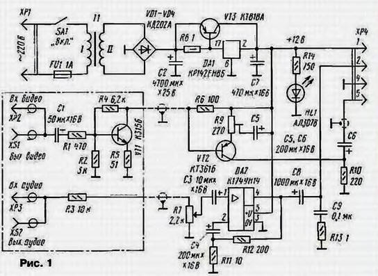
The second important node of the console - amplifier 3H on a chip of DA2. and the third two-stage amplifier transistors VT1, VT2. Plug XP2, connect HR to the source of video and audio signals (e.g., VCR), and to the jacks XS1, XS2 - consumer (say, TV). The video signal comes through capacitor C1 and resistor R1 to the first stage amplifier. Due to high the input impedance, it has virtually no impact on the level the video signal at the output of the source.
From the output of the first amplifier stage the signal is fed via a coaxial cable to the second cascade, and released on the monitor. Console connect to it using connector HR. The video level adjust trimpot resistor R9.
The audio signal through the resistor R3 and the shielded wire is fed in alternating the resistor R7 (volume control), and with its engine - in amplifier 3H. Output the signal amplifier through the capacitor C8 and the pin 2 of the connector HR comes on dynamic head (its findings are connected to the pin 2 and GND), installed inside the monitor.
Instead of the transistor VT1 is permissible to use any other of the series KT312, KT315, CT, CTS, and instead VT2 - any of the series KT361, CT. As VT3 you can use any of the specified in the scheme of the series. Rectifier diodes can be any that admit a current of at least 2 A. HL1 Led (power indicator consoles) - any compact. Oxide capacitors C1-C8 - K50 series, S9 - K10-17. K73. Variable resistor R7 - SP-1, trimpot R9 - GPA-3. SDR-19. permanent - MLT. C2-33. Socket XS1. XS2 and plug XP2, HR - type "Tulip", connector JR - five-pole, mating connector of the monitor (pin 5 must be connected with jumper 346 on the display Board). Transformer is applicable any, providing for the winding II voltage 15… 17 V At a current load up to 3 A.
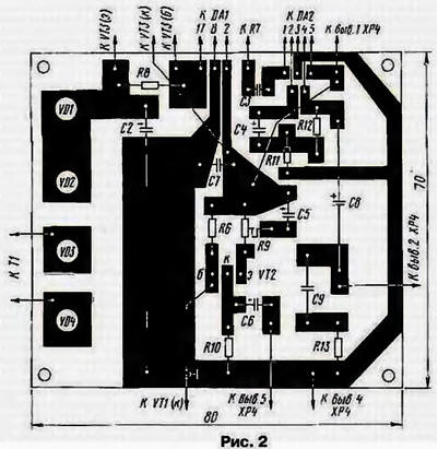
The nest details of the first stage amplifier and a resistor R3 is placed in separate housing and are mounted by a method of surface mounting. Case feature near the VCR or the TV. Most of the rest of the parts mounted on a printed circuit Board (Fig. 2) of one-sided glass material. Both the chip and the transistor VT3 supply heat sinks.
The establishment of consoles comes down to setting the required level of the video signal the adjusted resistor.
If you can use a monitor with a built-in or supplied with the unit the diet, which is the MS monitors-6105.05 - MS-6105.08). design consoles simplified amplifier 3H and the amplifier is fed from this block, and all the details placed in the display case.
A prefix can also be used with the tuner on the VCR or view the videos.
Author: I. Nechaev, Kursk