


")

Due to significant expansion of models of TVs used, different VCRs and the increase in the number of channels in bands VHF and UHF, it is of interest the possibility of revision of many old and some new vehicles to the level of dual-band sound with a remarkable improvement in its quality. This will be discussed in the article.
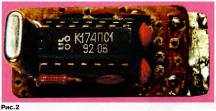
When you try to eliminate the shortcomings of the unit "clean" sound (BCS) and durstan-dard The HRC (standard tuning circuit of the television and the need for manual switch), which is described in detail in [1], was developed by pretty simple and sustainable second Converter if of sound. Its schematic diagram is depicted in Fig. 1 (about the symbols in parentheses will be discussed further), and the appearance presented on Fig. 2.
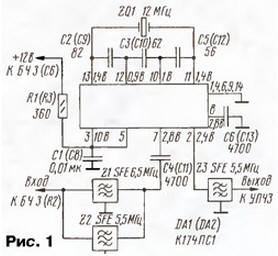
The main purpose of the Converter - convert the second if of sound 6.5 MHz in the second inverter of 5.5 MHz. However, it can convert and Vice versa: 5.5 to 6.5 MHz. In this case, the Converter with an equivalent quality of sound TV works on both UPCS with a FC of 5.5 MHz and UPCS with a FC of 6.5 MHz. You only need replace piezoceramic filter Z3 on the appropriate frequency or exclude him in the presence of a filter at the input of UPCS. The ability of the Converter in both versions are due to the choice of crystal frequency connected to the terminals 11 and 13 of the chip DA1.
To ensure the required functions in the Converter employs a dual balanced the mixer on the chip CPS (DA1). The signal of the second inverter audio via parallel included piezoceramic saw filters Z1, Z2 and capacitor C4 is supplied on pin 7 of the chip. As exemplary voltage has a frequency of 12 MHz (findings 11 and 13 of the chip), the output of the Converter (pin 2) get a differential frequency of 5.5 MHz at the input signal frequency of 6.5 MHz. If second if sound equal to 5.5 MHz at the input of the Converter, there will be a difference frequency output signal of 6.5 MHz, and it will be delayed piezoelectric filter Z3. However, the yield Converter free to the input signal frequency is 5.5 MHz.
Therefore, in the Converter ensures that the automatic reception of signals as standard D/K TV sound accompany, and B/G.
Piezoceramic filters Z1 and Z2 completely suppress the image signals to the input of the Converter and prevent signals of the second inverter of sound in the tract image.
The capacitor C3 in the Converter - corrective. Capacitors C2 and C5 set the mode the work of the local oscillator. To them increased requirements for stability capacitance at the operating frequency.
Installation of the Converter is performed unilaterally on a foil circuit Board, drawing which and arrangement of parts therein shown in Fig. 3. Capacitors can to be applied to any ceramic, the dimensions of which provide the possibility of install on the Board. Resistors - MLT.
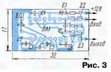
With proper installation, the Converter requires no configuration. On the pins fixed voltage indicated on the diagram. Consumed Converter current does not exceed 2.5 mA.
The operation of the Converter was assumed only in conjunction with BCS, however possible independent use of the Converter with its input signal of the second inverter sound good stability and protection from impacts components of the video signal.
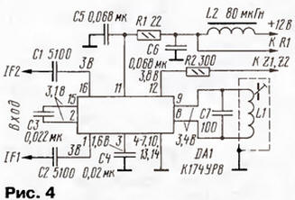
As a result of constructive combining the Converter with BCS was obtained dual-band block "clean" sound (DBCS) where there are no flaws, noted at the beginning of the article. Schematic diagram BCS for such use depicted in Fig. 4. It is connected to the Converter, assembled according to the scheme in Fig. 1, moreover, the numbering of parts in this case is shown in parentheses.
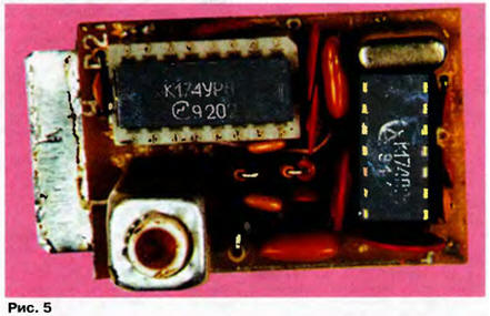
Appearance DBCS shown on the picture Fig. 5.
The main purpose of unit - automatic provision of sound in the video and still two standards D/K and B/G. This was possible, thanks the execution of the function block discharge from PCTV first if of sound 31,5 (32,5) MHz, it conversion to the second inverter 6,5 (5,5) MHz and converting the second AC motor drive sound 6,5 MHz 5.5 MHz. In addition, DBCS can improve the quality ("clean") sound of TV programs due to emission of a sound carrier 31,5 (32,5) MHz mode first if full level after the channel selector. It significantly increases the sensitivity and noise immunity of the radio channel television receiver. When installing the unit does not require any modifications or adjustments of the apparatus. The unit has a minimum size and is powered by a source DC voltage of +12 V. the consumed current does not exceed 35 mA.
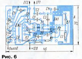
With symmetrical output IF1, IF2 channel selector signals of the first inverter image and sound arrive at the balanced input (pins 1 and 16) chip DA1 (see Fig. 4) and in it are processed. It should be noted that when unbalanced output of the selector IF2 input (pin 16) of the chip DA1 connect to GND via a capacitor C1. When configured for the desired the frequency of the circuit L1C7 connected to the terminals 8 and 9 of the chip DA1 allocated the signal of the second inverter sound of 6.5 or 5.5 MHz through piezoelectric bandpass filter Z1 or Z2 (Fig. 1) saw comes to the input (pin 7) of the chip of DA2 Converter second if of sound and is further treated in it. Requirements for the parts, fastening and installation DBCS similar requirements for BCS [1]. All elements of the unit are mounted on the PCB of one-sided foil fiberglass, the drawing of which and placement of parts therein shown in Fig. 6.
If the unit is not installed piezoceramic filter Z2 5.5 MHz, UPCS apparatus the wire is not regular shut off, and the output DBCS is connected to the input UPCS without breaking the installation. In this is versatility and variety when it manufacture.
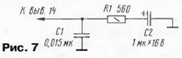
Chip CUR interchangeable analog TDA2545 [2] PHILIPS. But it is possible to use the chip CRUR with the following features include. Findings 4, 5, 7, 10 leave free, findings 3, 6, 13 connected to the common wire, and to the output 14 of the chip is connected RC circuit for the circuit shown in Fig. 7. All other connections are the same as in the diagrams Fig. 1 and 4. Chip CRUR also interchangeable analog TDA3541 [2] PHILIPS. Application chip CAR due to its accessibility and low cost.
Adjustment unit in the apparatus is only setting circuit L1C7 detector chip DA1. His podstroechnik achieve the best clean sound and the maximum volume. Setting precise on all the working channels up to receiving silent sound.
The purpose of conscious application DBCS radio Amateurs in various devices (foreign and CIS countries) will look at some practical options connection with consideration of the peculiarities of the structure of radio channels [3]. The diagrams Fig. 8-10 presents options for adding DBCS in TVs models 1512, 4462, 4465 PHILIPS respectively. Numbers in blocks shown appropriate conclusions devices or elements in them. Forming a chain of nodes is omitted. The rupture conductors indicated by a cross.
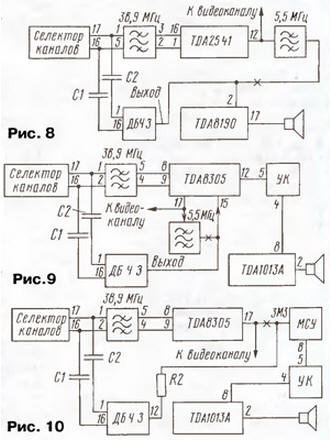
If DBCS assembled in full compliance with the schemes in Fig. 1 and 4, when it is mounted from the desired output chip disable device staff saw filter (Fig. 8 and 9), and the output is connected to the output DBCS.
In the case of manufacturing DBCS without filter its output Z2 fluster shown to the pins of the chip without disturbing the regular mounting apparatus. In this case obtained in "pure" form of the so-called quasi-parallel channel. According to the scheme in Fig. 9 shows that the radio channel model 4462 contains other than in the diagram in Fig. 8, chip. Moreover UPCS is the primary processor after a selector channels processing PCTV. Also included in radio channel switching unit (CC), which takes the input of the amplifier 3H signal or VCR, or the radio channel. Under the criminal code has no direct relationship, it may be consulted in [3].
Channel TV 4465, as shown in Fig. 10, includes Multisystem device (IAS) sound, which will tell more detail. The knowledge of the essence of its functioning will allow us to understand the meaning use DBCS in this model.
A simplified schematic diagram of the LSG is depicted in Fig. 11.
The purpose of this device - ensuring usestandartsession sound. The path gain and detection on the chip TBA120U (7410) the sound if signal is fed through the wire A through capacitors 2303, 2304 and four-photon input filter. Its component filters are switched by diodes 6403-6406 when exposed to a signal select the TV system, coming from a management node of the TV to the output 2 of the first operational amplifier circuits 7405.
To ensure bsestandardosc.h detection, frequency the detector chip TBA120U applied circuit with varicap 6435 - 6437, changing the frequency settings. Restructuring occurs when the second operational amplifier (pins 5-7) 7405 chip simultaneously with switching input filters IAS Mode adjustment trimmer set resistor 3426. Via pin 8 of the IC 7410 audio signal goes to the criminal code (see Fig. 10) apparatus.
Why in this sustentation TV, you need DBCS? It is necessary, first just to improve the technical characteristics of the radio channel. For this purpose (case 1) from DBCS remove all the saw filters and connect it according to the diagram in Fig. 10, disabling regular wire from the entrance of the LSG In this case, the Converter is also not use.
In addition, when the failure (case 2) of the first operational amplifier chip 7405 (with working the second op-amp) in the LSG cannot switch it input filter to the desired frequency sound. In this situation the output DBCS performed in full compliance with the schemes in Fig. 1 and 4, connected to the output 14 of the chip TBA120U when disconnected from it staffing the wire. This ensures high quality audio dual-band support with subcarriers of 31.5 and 32.5 MHz.
And finally (case 3), if were out of service both OS in the chip and no 7405 possible to replace it, and the chip ТВА120U remains operational, DBCS connect the same way as in case 2. However, from terminals 7 and 9 of the detector chip TBA120U off the regular circuit and connected to the circuit, similar L1C7 in DBCS. It configures the podstroechnik to obtain the most "clean" sound at the output of the radio channel.
In Fig. 12 shows a block diagram of a radio channel TVs in which video processor chip is TDA8362 (or its modifications). It is known that she has several disadvantages as part of the sound channel. They relate to the use in her broadband differential amplifier the if sound, a frequency demodulator with system PLL and unsuccessful ones constructive input arrangement UPCS (conclusion 5) and output PCTV (pin 7). Even when a slight noise at the entrance UPCS it leads to disruption of PLL and, as a consequence, interfere with the loudspeakers.
The use DBCS these TVs provides increased robustness UPCS by receiving at its input (pin 5) maximum allowable chip the signal level. When this input block is not exposed to videomastasia, as it is allocated in the first mode the FC level and full is detected in DBCS. Moreover, improve the technical characteristics of all the radio channel.
The options considered will freely allow hams to resolve issues use DBCS.
Literature
Author: E. Hajdel