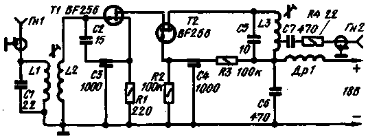
Antenna amplifier (see figure) allows for 12-15 dB to raise the level of TV signal meter band. He made two field-effect transistors (CP). The signal from the antenna is fed to the input circuit L1C1, tuned to the mean frequency of the received signal. With the coil 13, the voltage applied to the gate of the transistor T1. The transistors T1 n T2 is enabled by cascadei scheme. This provides high gain and eliminates parasitic feedback from the amplifier output to its input. The load transistor T2 is a resonant circuit L3C5. With part of the coil L3, the signal is fed to the nest GN.

Coils L2 and L3 is wound with a wire diameter of 0.9-1 mm. the Distance between adjacent coils must be equal to the wire diameter. The coil L1 is wound between the lower coils of the coil L2 wire of smaller diameter. Coil L1 contains 2 coil, coil L2-5 turns. L3-6.5 turns (removal from the round 5 top). The diameter of the armatures coils 6-8 mm. Trimming cores made of HF ferrite. Choke DR1 contains 12 turns of wire with a diameter of 0.12-0.15 mm, is wound on the frame with a diameter of 3 mm round.
Literature
- "Practical Vireless" (England), 1974, November
- Radio No. 6, 1975
Publication: N. Bolshakov, rf.atnn.ru


