


")

A schematic diagram of such a device is presented in figure 29.
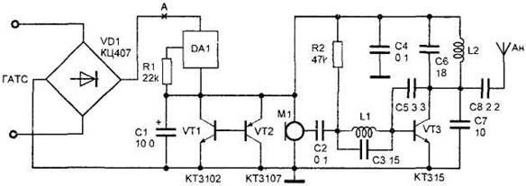
Figure 29. Wireless microphone-radio repeater powered from the telephone line.
Rectifier bridge VD1 type CC is connected in parallel to the telephone line regardless of the polarity of the line voltage. Line voltage when on-hook has a value of about 60 V. This voltage is applied to the power unit, which is made of a chip of DA1, the resistor R1, the capacitor C1 and transistors VT1 and VT2. DA1 chip type CZ is a current stabilizer operating at voltages of 1.8 to 120 V. the voltage Drop in the flow of constant current through the load during the charge of the capacitor C1 is limited by the analog low-voltage Zener collected on transistors VT1 and VT2. While on-hook, the device works as a wireless microphone. The description of the scheme in wireless and its setup are given in section 2.1. When removing the tube a slight change of the current flowing through the load wireless microphone, causes a change in the operating point of the transistor VT3, and thereby performs frequency modulation of the radio microphone.
Transistors VT1 and VT2 can be replaced by KT315 and KT361 respectively. The capacitor C1 with minimal leakage current. Configuring the power supply is to install a resistor R1 of the current flowing through the load. The current at the point And must not exceed 1.5 mA.