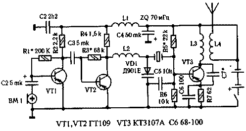
As antenna wireless microphones used a piece of antenna cable 75 Ohm with a diameter of 3 and a length of 185 mm. the metal core is soldered directly to the capacitor 9, the braid serves as a fastener. The microphone signal increases two-stage amplifier 3H on transistors VT1,VT2. The master oscillator is made on the VT3 transistor. Frequency modulation of the carrier is provided by a varicap VD1. Resistors R5,R6 in the base circuit of the transistor of the generator determine its mode DC. Capacitor C7 determines the necessary mode of generation providing positive feedback. The capacity of this capacitor should be selected according to the maximum current consumed by the generator, and then the resistor R5 to set the current to about 25 mA, because at higher current transistor VT3 cannot work.

When customizing, it is advisable to place C7 to include a trimmer capacitor 8 to 30 PF, and the resistor R5 - turn trimmer resistor of 100 ohms.
The frequency stability of the generator depends mainly on supply voltage. To improve, you can use a voltage regulator b...9 V. to Stabilize the oscillator frequency and other method. To be precise, the instability of the carrier frequency in the oscillation of the operating point of the transistor output stage of the amplifier 3H changing the voltage. The position of this operating point determines the reverse bias voltage on the varicap VD1, and hence its original capacity, which ultimately will change not only under the influence of a sound signal, but also when you change the voltage. The variable capacitor also connected in series with the crystal and with it determines the frequency of the generator. Therefore, it is possible to Supplement the scheme of a transmitter device that provides a constant voltage offset of the variable capacitor ( Fig.2 ), the value of which can be adjusted by the resistor R1.
The circuit R2,VD1 is a regular parametric stabilizer. Capacitor C1 provides decoupling of the cascades DC.
When mounting the transmitter used fixed resistors MLT - 0,125, oxide capacitor K50 - 35; fixed capacitors of ceramic compact, for example km.
Inductors L1, L2 can be applied standard, for example, D is 0.1, with an inductance of 15...30 mH or make yourself. For this purpose, the resistors MLT - 0,5 a resistance greater than 100 ohms need to be wound over the entire length 30 ...50 turns of wire PEL of 0.1. Contour coil L3 is wound on the frame with a diameter of 8 mm and contains 6 turns of wire PEL of 0.8. On the same frame and the same wire is wound and the coil L4. Its winding comprises 3 coils and is placed at a distance of 1 mm from the winding of the coil L3.
A few words about the antenna. For its production uses cut 50 Ohm long cable 10... 12 cm, clean it with insulation and braid and pull out from the Central vein. Then, on the transmitter place the socket connector WITH R - 50 - B to which is attached a coil L4 (antenna connector). In the connector plug clip segment processed in the described way cable. It now remains to reel across a long piece of cable round wire enamel insulation of 0.6 - antenna ready . You should only insert the plug into the aerial socket of the transmitter.
In an extreme case as an antenna, you can use metal rod of length 30...50 cm.
In the operation of the transmitter , it was observed that if during the transmission to put his hand to GND, then the radiation power of the transmitter increases. In other words, the body of the operator plays the role of a counterweight to the antenna. If the transmitter is assembled in a plastic housing, a counterweight may be provided, connecting to a common wire a piece of wire of length 1 m.
If the casing is metal, it must be connected to GND. The counterweight in this case is not needed because its function will be performed by the operator, in whose hands is the transmitter. As a microphone you can use any small-sized microphone than coal.
Naturally, the receiver sensitivity will affect the range of communication.


