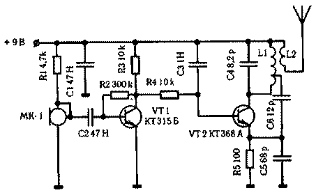
A distinctive feature of the scheme wireless microphones, represented in the figure is that the amplified signal with 3H collector of the transistor VT1 is input to the RF generator VT2 without the separation vessel, in view of what the working point of the generator's DC is determined by the working point VT1, that is, the resistor R2. The main task when setting up wireless microphones is the tradeoff between current consumption of the generator and the amount of distortion in the circuit 3H.
As transistor VT2 is desirable to use high frequency type KT368, CT. For a frequency of 175 MHz, the capacitance C4 is 6.8 PF, L1 - 5 turns silvered copper wire with a diameter of 0.56 mm with a branch from the third round. The winding diameter is 5mm. the Coil L2 - 2 turns of wire sew - over 0,25 L1.

In order to reduce the size, this unit is applied to a resonant antenna. To make this kind of antenna, need to take a long plastic tube with a diameter of 3 mm and wind it in a number of wire PEL - 0.25 mm 65...70 turns. Then connect the antenna to the output of the generator, and atrativa one turn, control the resonance pointer field indicator. The scheme operates in a wide voltage range from 1.5 to 15 V, and the frequency of the output oscillations, when using a non-resonant antenna is changed in a small range. With a current consumption of 10 mA, the receiver sensitivity of 1 μv allows you to listen to the radio microphone at a distance of 500 m.


