In all constructions used high-performance small-sized electret type microphones MKE-332 containing a built-in preamp FET.
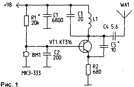
Figure 1 shows the scheme of wireless microphonesin the base bias circuit of which is included as a controllable resistor electret microphone.

As an antenna used cut flexible stranded wire of length 20...40 cm power consumption of approximately 1 mA.
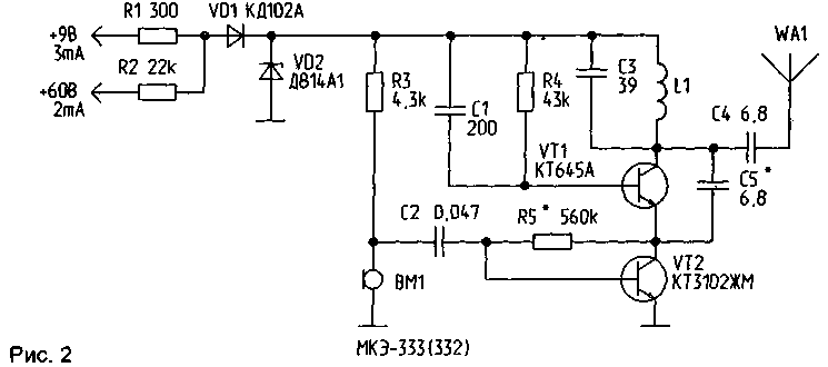
The device shown in figure 2, is a telephone mains parallel type and designed to transmit audio signals for high-frequency channel. The device can be powered directly from the telephone line 60, while drawing the current to 2 mA; when removing the handset (the supply voltage) the radio microphone is muted.

In the scheme used chastnoe switch transistors, wherein for signals of low frequency load in the collector circuit of the transistor VT2 is a high-frequency generator configured transistor VT1. In turn, for high frequency currents in the emitter circuit of the transistor VT1 used cascade gain on the transistor VT2.
When you power the device from the telephone line to connect the antenna is not required because the telephone line plays the role of a fairly long antenna. Reception of high frequency signals is possible on a portable FM receiver along the telephone line; when you remove from the line for a few meters, the signal decays rapidly. The scheme provides the opportunity for standalone or redundant power supply from a battery voltage of 9 V. In this case, the device becomes an ordinary wireless microphones, and to him you must connect antenna. The unit is protected against wrong connection of power supply and over voltage - diode Zener diode VD1 and VD2. So, when you reverse polarity, the device will not work and if you apply voltage 60 V with telephone line to the input of the power supply 9, a telephone line through a resistor R1 and a Zener diode VD2, and also due to its internal resistance limits the current, short circuit, and circuit elements are protected.
The device has dimensions of HH mm. the Transistor VT1 can be replaced by KTM, VT2 - CTG.

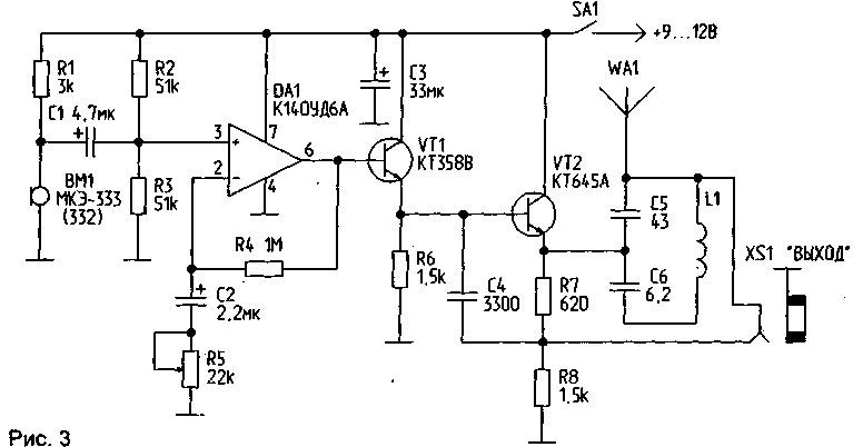
Figure 3 shows the scheme of the multifunctional purpose. When included in the socket XS1 "EXIT" high-Ohm (200 Ohm) telephone earpiece or external connection ULF (e.g. tape recorder) device is a highly sensitive low-frequency amplifier with adjustable gain. In this mode the device can be used as a hearing aid. When connecting an electret microphone instead many-turn coil with ferrite, permalloy or iron core, the device may be used to provide inductive connection, readout of phone calls, reading the audio signals from the handset or zvonkova coil telephone search sources of variable magnetic fields, etc. If the phone plug is removed from socket XS1 device is automatically converted into a radio microphone, a high-frequency generator which is made on the transistor VT2 CTA. Potentiometer R5 determines the amount of deviation customroleprovider signal.
All schemes used frameless inductor having an inner diameter of 4 mm and containing 5 turns of wire sew-2 with a diameter of 0.56 mm. Required operating frequency is set by shifting/splitting of turns of the coil, varying the number and diameter of coils, the selection of capacitor resonant circuit. The case of the electret microphone in all cases is connected with the common wire.
M. SHUSTOV, 634024, Tomsk, St. 5-OI the Army, 9 - 208.
(RL-2/97)


