


")

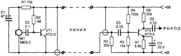
Figure 32. Small external microphone.
The device is divided into two parts. One of them collected on the VT1 transistor KT315 type on the common-collector, and the second on the VT2 transistor in common-emitter circuit. The signal taken from the electret microphone with amplifier type FEM-3, is fed to the base of transistor VT1. The load of this stage serves the resistor R3 is located in the second part of the device. This resistance is necessary to supply power to the input stage transistor VT1 with a minimum number of connecting wires. The signal taken from the resistor R3, through the condenser NW, is fed to the audio frequency amplifier, assembled on the VT2 transistor KT315 type.
Both parts of the device are connected with shielded wire. Moreover, the negative voltage of the power source and the audio signal received by the Central conductor of the wire, and a positive voltage is supplied through the braid.
As the microphone Ml, you can use any electret microphone with amplifier. The VT1 transistor KT315 type it is better to replace the low-noise transistor KT3102. The resistors in the circuit - type MLT-0,125. As the power source uses a rechargeable battery to a voltage V. 6-9
The device configuration consists of setting the operation modes of the transistors VT1, VT2 by adjusting resistances of the resistors R2 and R4, respectively. In this case, the collector current of each transistor should be about 0.1-0.2 mA.