


")

In the 90-ies in connection with the expansion of the network of terrestrial television broadcasting and the increase the number of active channels has dramatically increased the interest of users to multi-channel television antennas are capable of, without any of the switches to accept EfE programs in the range of VHF and UHF. From mid-decade on the market to do Polish compact television antenna ASP-4WA, ASP 8WA (CX-8WA) firms ANPREL, serves a variety, ELECTRONICS, etc., satisfying (in varying degrees) the requirements of this procedure. Antenna quickly gained popularity, and now in the operation is a fairly large number of them.
Individual television antennas ASP 4WA, ASP 8WA are flat dipole design with common mesh screen-reflector. They are active, i.e. electronic amplifiers are mounted directly on the antenna and eating at the feeder decrease. Many of the characteristics of antennas, such that in specifically, as the gain and the bandwidth obtained through the use of antenna amplifiers. Therefore, on the parameters of the last depends largely on the quality of the reproduced television image.
For active antennas ASP different manufacturers produce a whole range unified antenna amplifiers under various trademarks and rooms. Structurally they are all the same: in the form of a small printed circuit Board (approximately 60x40 mm) surface mount micronutrients. The Board is made for automated SMD technology and completely reliable, due to multiple control. Because of the unique design of these antenna amplifiers is called lamellar.
About circuitry, parameters, faults and repairing a large number of antenna amplifiers SWA is explained in detail in [1]. However, firms that produce these amplifiers, improving their products, and currently there are many new models: SWA. S&A, GPS, RYE, etc. Their options are undoubtedly of great practical interest both for the owners already operating and antenna wanting to improve image quality, and for those who decided to buy a new antenna. In addition, the amplifiers can work with other types of antennas, for example, automatic process, wave channel, etc. (subject to agreement input resistance).
Antenna amplifiers have a number of characteristics that are relatively be divided into two groups: General and individual. Common include: input and output resistance (300 and 75 Ohms, respectively), the supply voltage (9… 15 In at nominal 12V), work frequency channels (1-68 channels, with rare exceptions). Thanks to the common parameters provided interchangeability amplifiers.
However, to assess the quality of the amplifier is also important individual parameters, distinguish one amp from another, in particular, noise and amplifying. Information about them is not always available, although in recent years it has become partially put in trade documentation to the antennas. Fully it is stated in the company catalogues, which are difficult to acquire even for the firms trading antennas wholesale.
With the right antenna amplifier should know at least two individual parameters: the noise figure and the given gain Ku. It is highly desirable to also submit and view its frequency response.
Utmost importance when selecting the amplifier has a noise figure: he must to be as small as possible, and certainly lower than the input stage of the TV [1]. Modern antenna amplifier should have a noise figure less than 2 dB.
The second parameter (gain) is calculated according to the methodology described in [1] based on the signal loss in the cable and passive splitters (if they is). Choose antenna amplifier nearest to the calculated value coefficient Ku. Its increase above calculation gives the effect while the reduction of the noise level, otherwise only increases the risk of self-excitation and overload of the amplifier strong signals from nearby stations.
It is necessary to consider also the dependence of the coefficient Ku frequency which is determined by the actual frequency response of amplifiers Each of them has its own distinctive look AFR. Thus, the amplifiers SWA and RYE have a single smooth maximum (hump) at the frequency about 600 MHz (raise the gain reaches 6… 10 dB). The S&A and RA characteristic two: the second ascent of amplification in 3…5 dB is located on a frequency of about 100 MHz, i.e., at MB. View AFC allows you to select the amplifier in depending on reception conditions with the aim of improving sustainability and noise immunity at the expense of gain reduction in the non-working parts of the range. Specified in the documentation gain, usually refers to range DM, MB at frequencies it can be significantly lower.
Most new amps are collected in a traditional two-stage scheme MA-MA. Consider the circuitry, parameters, and frequency response of some new models of different brands.
Amplifier SWA-555, schematic diagram of which is shown in Fig. 1, is an aperiodic two-stage amplifier RF bipolar microtransaction T (BFG-67) or BFR-91A.
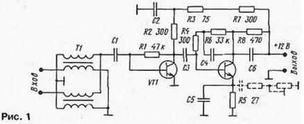
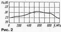
The first cascade - broadband without correction. In the second cascade has a correction: the capacitor C5 in the circuit current EP of the transistor VT2 provides the AFC decay of the low frequency operating range [1], and the capacitor C4 in the circuit OOS voltage limits the gain at the top frequencies outside the operating band. The frequency response of the amplifier shown in Fig. 2.
In General scheme of the amplifier SWA-555 and SWA-9 almost completely coincide ( first, only there is no LC filter in the power supply circuit and changed some values passive elements). Therefore, frequency response of amplifiers close. However, when using in the first stage of a low noise transistor BFR-91A (Cs=1.6 dB) amplifier SWA-555 has a lower noise figure.
The S&A more complex circuit frequency correction in both cascades. In S&A-130, S&A-140, a schematic diagram of which is presented in Fig. 3, the chain EP voltage of the cascade transistor VT1 entered the serial circuit L1C2. Its resonant frequency is chosen such that the gain of the first stage decreased on the upper frequency range that contributes to the sustainability amp. To extend the bandwidth correction factor of the circuit L1C2 reduced the resistors R1, R3. which provide the necessary DC current database transistor VT1.
The second stage is equipped with a double RC circuits R6, R7, C6 and R7, C4, C5 to the emitter circuit of the transistor VT2 of changing the frequency response in the low frequency region. As a result characteristics of the amplifiers is obtained double-peaked, as shown in Fig. 4.
The rise the gain at the frequency of 100 MHz up to 3…4 dB. The failure between the humps have for frequencies 230…400 MHz, not used by terrestrial television channels. This the shape of the frequency response improves stability and noise immunity of the amplifier.
Other features of the S&A it should be noted the use of the input diode lightning protection VD1. Its efficiency is not very high, so the antenna it is recommended to ground.
Amplifiers PARADISE, as in S&A, applied LC-correction in both cascades. In the amplifier RYE-45, a schematic diagram of which is shown in Fig. 5, it is provided by two serial circuits L1C3 and L2C5 included in the the feedback circuits for the voltage of the first and second stages, respectively.
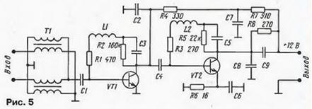
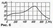
In addition, affect the formation frequency and the capacitors C2, C8. As a result, the hump in the frequency response of this the amplifier is more acute, with a sharp decrease at frequencies above 700 MHz, what can be seen in Fig. 6.
Amplifiers RA to consider in detail makes no sense, because they are similar the S&A, excluding the application of the input instead of the diode VD1 coil. View Frequency response of amplifiers RA and S&A is about the same.
GPS models are similar to the amplifier SWA-455, SWA-555 and differ only in the values of corrective elements in the second stage. By increasing capacity a blocking capacitor in the emitter circuit of the second transistor is achieved the increased gain at the phase frequency 100…400 MHz.
In some new models of amps to the emitter of the second transistor is connected additional chain of series-connected and constant trimming resistors and capacitor (in Fig. 1 shows a dashed line). Trimmer the resistor in this case you can change the gain in the lower frequencies range and therefore the frequency response of the amplifier. Unfortunately, the value of such controller correction is small, since the amplifier with extended antenna hard-to-reach.
The analysis circuitry and frequency response, of course, is not complete because, in addition to corrective circuits, frequency response is influenced by the relative position of the parts, the capacity installation, the strip lines etc. he nevertheless, according to the author, sufficient for a correct choice of the amplifier by referring to frequency response, and in some cases, and for self-adjustment by the selection of corrective elements.
From the analysis implies the following practical recommendations. Real view AFC amplifiers SWA and PARADISE is that they should be used mainly for the reception the remote stations to the UHF range. which amplifiers have a maximum gain. Due to low growth in MB such amplifiers (especially RNS) more resistant and better protected against interference at these frequencies.
For reception of weak signals MB, preference should be given to S&A, and RA GPS with a high gain on MB. This is especially important given that small antennas ASP own very little gain on MB range: the frequency of 50 MHz, for example, antenna ASP-8WA does not exceed 1 dB [2].
The main parameters of the new models SWA. S&A. PA, GPS, RAE (working frequency the interval f, the noise factor of CABG and gain Ku), taken from the network The Internet [2], as well as corporate directories, submitted to publish here table. When the divergence of information, it has the worst value. It is obvious that some new models achieved some reduction in noise (1.5 dB), but there are still quite a "noisy" amplifiers with X is 3…3.9 dB (SWA-31. SWA-32, S&A-110. S&A-120. RA-10), which is not recommended.
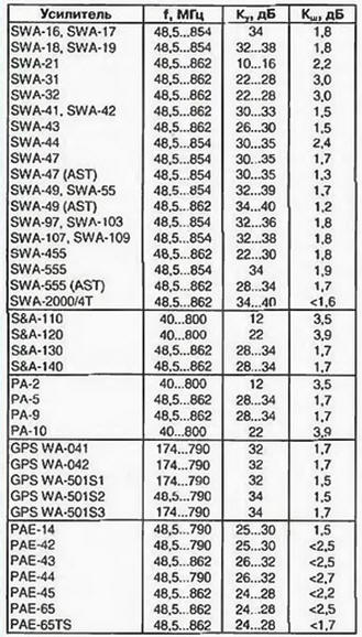
Manufacturers have so far failed to achieve a significant improvement in noise characteristics of most amplifiers. The best of the previous model SWA-7, SWA-9 had the coefficient Cs=1,7 dB [1]. He stayed about the same at the new amplifiers or decreased slightly, except models SWA-47(AST), SWA-49(AST). It due primarily to the fact that the circuitry and transistors used does not changed: at the inputs use the same microwave transistors T, V3, with 415 a cutoff frequency of 7.5 GHz and a noise figure of 3 dB [2] occasionally less "noisy" BFR-91A.
It should be noted impact on the performance of amplifiers not only the type of the first transistor, and the operation mode. From its collector current depends on the level self-noise, gain and the value of the active component of the input conductivity, affecting the degree of matching on input.
In most antenna amplifiers the transistor VT1 works when the collector current 1"=8…12 mA. This allows you to get pretty high gain and a good agreement with the input transformer T1, but not optimal for ensure small noise. Although based Cs=f(IC) used microarray unknown, but, typically, for silicon bipolar transistors microwave low noise is observed in the collector current 2…5 mA [3]. Consequently, there is a probability that when reducing the collector current of the transistor VT1 is possible to reduce noise while maintaining good matching at the input. This is indirectly confirmed by the fact that amplifiers PARADISE (only them) the current of the first transistor is reduced to 4 to 5 mA. for what if the transistors achieved a significant reduction in the level noise: according to information from the Internet ratio of CABG in these reaches amplifiers 0.8…1 dB.
As noted in [1], many antenna amplifiers SWA with great odds amplification is prone to excitation. This is due to the fact. to ensure the stability of aperiodic two-stage RF amplifier, assembled according to the scheme MA-MA, in the frequency band of 900 MHz is quite difficult. It would seem that further the increase in the number of stages doesn't make sense, because to achieve sustainability in this case is almost impossible. However, the market appeared amplifiers, collected on four transistors. Intrigued by this fact, the author acquired amplifier SWA-2000/4T. His is a schematic circuit composed of a circuit Board, presented on Fig. 7.
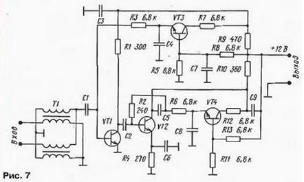
Analysis of the circuitry of this amplifier showed that it is assembled in the usual way on two transistors VT1 and VT2, is enabled with OE. The input signal is supplied to the base transistor VT1 is amplified in two trache and removed from the collector transistor VT2. proceeding through the transition, the capacitor C9 in the coaxial cable. The additional transistors VT3 and VT4 are active circuits that specifies the bias voltage at the bases of transistors VT1 and VT2. Since the transistors VT3, VT4 does not amplify the useful signal, for this purpose, the low-frequency and cheap chips 3F.
It is obvious that with such a construction characteristics of the amplifier SWA-2000/4T can't how-ever substantially exceed the parameters of two-stage amplifiers a similar correction (SWA-7, SWA-9. SWA-555, etc.), and it was confirmed comparative tests.
Summarizing, we come to the following conclusions. First, many of the new amps repeat circuitry and accordingly the characteristics of the older models. In this case a substantial number of the new development does not indicate its higher quality. For example, the amplifier SWA-555 in the parameters and the circuitry is the same amplifier SWA-9. The same applies to amplifiers, collected on four the transistors.
Secondly, among the new amplifiers can see the models really improved characteristics, implying the possibility of improving the reception quality. On noise best options it is possible to recognize the amplifier SWA-47 (AST), SWA-49 (AST), and, judging by the information on the Internet, amplifiers like PARADISE.
Thirdly, replacement antenna amplifier will lead to a positive effect only in the case of the use of the new model with a lower level of noise, the estimated value gain and appropriate frequency response.
In conclusion we can say that the model of antenna amplifiers manufacturers develop quite quickly and it is possible that by the time of the release magazine with this article, probably, will appear and the new, improved the amplifiers. In any case, the criteria for determining their quality and recommendations for the choice considered here and in [1], do not change.
Literature
Author: A. Pakhomov, PhD. tech. Sciences, Zernograd, Rostov region