


")

In the published article, the author, considering the amplifiers used in the antennas Polish production, different methods for their use in antenna-feeder tract.
Plate antenna amplifiers (PAHs) are part of the popular Polish TV antennas ASP 4WA. ASP 8WA (CX-8WA). They are printed cost size 60x40 mm surface-mount micronutrients. Under normal the inclusion of such an amplifier is mounted directly on the antenna: the input connected to the collecting line and the output to the cables by which it receives a supply voltage.
Currently release a lot of interchangeable PAHs brands such as SWA, GPS. RA. RYE and others of Their circuitry, characteristics, characteristics of the different amplifier and repairs have already been reviewed in the magazine 11.[ 2]. Here offers unusual PAH, which refers to any the inclusion of separately from the antennas ASP.
It should be noted that PAHs are "ready to eat" electronic components and, given their relatively small price (1.5…2 dollars.) becomes clear the desire of hobbyists to use PAHs in their designs antennas. And they are often more effective and better adapted to specific conditions of reception than the antenna ASR Only problem which you will need to solve it, - coordination input impedance of the antenna with an input impedance of amp.
Consider first, as agreed in the ASR antenna input POW included balun-matching transformer on a ferrite ring To 10x6x2,5. It has two winding - two-wire long line, containing three turns each. This transformer on long lines (TDF) has high efficiency (up to 98 %), small size and wide range of operating frequencies [3]. When you distribute accept fluctuations in the currents flowing through the conductors of the lines are equal and opposite in direction, and this means that the magnetic circuit is not magnetized and losses in almost no. On the other hand, the presence of the magnetic core increases the inductance of the windings, eliminating them shunt effect on the antenna and the load. On the distribution of fluctuations the magnetic circuit is not affected, as provided mode traveling wave.
The scheme of inclusion of TDF antenna ASP is shown in Fig. 1. It has balanced input (point a. b, C) and unbalanced output. For him fair ratio specified in [3] Rr = n2RH; U1 = nU2. p = nRн, where R, - the resistance of the generator is equivalent to the antenna in Ohms; RH is the resistance load, Ω; n is the transformation ratio; p - wave impedance two-wire line in Ohms.
Some values in formulas require clarification. Thus, the transformation ratio numerically equal to the number of windings of TDF, the resistance generator to the antenna working at the reception, is equal to its input impedance, and load impedance - input resistance PAHs. Antenna impedance is about 300 Ohms, and the number the windings of TDF or two. Substituting in the formula, we obtain: U2=0,5 U" RH=75 Ω, p=150om.
Consequently, as a result of matching the voltage of the useful signal is halved, and the input resistance - four times, and the latter is transformed into a close to standard (75 Ohms). From this it follows, the active component of the input impedance PAHs close to 75 Ohms, i.e. its the entrance actually agreed with a characteristic impedance of the coaxial cable. Output the amplifier is also designed for this load. As a result, we can conclude: PAHs without TDF able to work effectively when you enable it in the gap coaxial cable without additional approval.
To assess its effect on the properties for the removal of TDF, let us dwell on the frequency characteristics of the latter. Although TDF has no boundary frequencies, in fact its lower operating frequency f, is limited the inductance of two-wire lines which is determined by the formula given in (3]: l b = w2μS/250dcp (µh), where w is the number of turns on the magnetic core; μ - the relative magnetic permeability of the magnetic core; S - the area of cross cross-section of the magnetic circuit. cm2; dcp - the average diameter of the ring, see the bottom the operating frequency is equal to (see (3]): Fn = R/2lfl (MHz).
The calculations lead to the following results: l b = 0.68 mH, FH = 220 MHz. This the frequency value shows that almost in all range MB the transformer does not operate in an optimal mode. This means a reduction in IPM and transfer coefficient, especially noticeable at frequencies of 1 - 5th television the channels specified in [4].
A natural question arises: why did the designers not lowered the frequency FH simply increasing the number of turns of the two-wire lines? The fact that this prevents the maximum length of two-wire line Lmaх, which should not to exceed λ/8 [3]. For the upper operating frequency of the UHF range obtained Lmaх = 4 see that is the length I have the line transformer T1. The increase in the number of turns will inevitably lead to excess Lmaх and affect the parameters of the transformer on the upper frequencies of the UHF range. Therefore, to provide optimum the work of TDF on all TV channels will fail. Therefore, designers preferred to obtain maximum efficiency and the coefficient of transmission in the UHF range. This transformer and the entire antenna can be called a decimeter.
Obviously, matching TDF always affects the parameters of the antenna on one of the ASP brim full TV band. However, other matching device yet less broadband and unsuitable for such antennas. To do the same without harmonizing and balancing in antenna similar to the antenna with ASP asymmetric PAHs. Although, of course, known antenna amplifiers, not requiring matching devices [4], but that's another conversation…
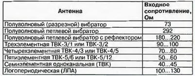
A number of prominent variety of antennas [5], are listed in the table, input the resistance close to the same parameter of antennas ASP, has a half-wave the folded dipole. To him PAHs (TDF) connect without any alterations. And often practice connecting a conventional half-wave vibrator to points AVV TDF inefficiently because their input impedance differ by four times.
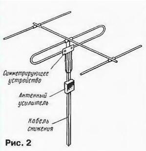
The above conclusion allows us to offer almost any simple antennas the method included PAH-without TDF, in the gap of the coaxial cable. While the input antenna mount the balun-matching device, described in [5Y. U-knee, half-wave loop, shorted loop, RF the transformer or the adder (with two antennas), and the amplifier include will be watching it. as shown in Fig. 2 (for example conventionally depicted antenna "wave channel").
Modifications of the amplifier is minimal: he removed from TDF. Enough even unsolder the leads from the pads to which are soldered the capacitor C1 [ 1.2]. do not delete TDF. Then cut the input coaxial cable required length to connect the antenna with PAH. The center conductor of one end cable soldered to the pad connected to the output capacitor C1, and the braid to the wire of the amplifier. The second end of the cable connect with matching-balancing device antenna. After that, the amplifier is attached to the mast (screw or clip) and is connected to its own output cable clamping device on the Board. The amplifier is carefully sealed, especially in places where soldering and connecting cables. The method of supplying it with voltage regular, not once described on the pages of the magazine.
The removal of TDF aligns the frequency response of the amplifier in the interval and increases MB its transmission coefficient. Most PAHs are stable in this mode. If the amplifier is oscillating (in models with high gain, as noted in [ 1 ]), should slightly reduce the supply voltage.
An additional advantage of this method of using PAH - ability varying installation locations: close to the antenna before placing in a closed the room. In the first case, we have a maximum ratio signal/noise, the second is a reliable protection of the amplifier against weathering, extending its service life. At small length segment of the input cable (5 m) or using cable RK-75-9-13. having a low linear attenuation, the amplifier can set under the roof (in the attic). Real poor signal quality when this will be minor and only visible on the upper UHF frequencies.
In conclusion, this method of turning on PAHs simple, versatile and gives good results. Of course, there is another path - calculation (using the methodology proposed in [3]) and production of the new TPD. matching specific antenna the input of the amplifier.
Literature
Author: Anatoly Pakhomov