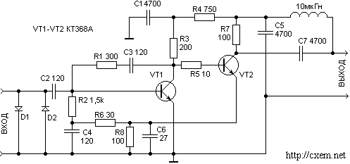
The figure shows the circuit of the antenna amplifier is designed for amplification of signals of all 12 channels MB. The gain is 25 dB at a voltage of 12 V. the current consumption of 18 mA. Anti-parallel connected to the input diodes protect the transistors of the amplifier from damage by lightning discharges.
Both cascade is collected under the common-emitter circuit. Capacitor C6 provides correction of the frequency characteristics of the amplifier at high frequencies. Stabilization mode transistor amplifier covered by negative feedback from the emitter of the second transistor to the base of the first. To avoid self-excitation of the amplifier due to parasitic feedback between the stages through the power supply used by an isolation filter R4 C1. The amplifier shall be installed in close proximity to the antenna and power is supplied to it through the junction cable.

Author: Nechaev, I.; Publication: www.cxem.net


