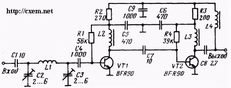
Simple design two-stage wideband antenna amplifier is designed to amplification of television signals in the UHF range.
At the input of the amplifier included custom bandpass filter L1C2C3 with a bandwidth of about 50 MHz in the range from 21 to 60-th channel of the TV band. Transistors VTI and VT2 connected in the circuit with common emitter. The first stage operates at a current the collector of transistor 7 mA and to a greater extent determines the parameters such amplifier as noise and cross-modulation. The second cascade determines the overall gain is 25 dB. The collector current of the transistor VT2 is selected in the range of 25 mA.

The input and output of the amplifier is single-ended and designed for connecting a coaxial cable with wave resistance 75 Ohm.
The power is carried out by a voltage of +12 V and is fed through the feeder. The inductor has an inductance L4 and 10 μg wound on ferrite ring cores. Coil L1 is made silver plated wire diameter of 2 mm, has a halfway and molded on the mandrel with external 4 mm diameter. Inductors L2 and L3 have 3 coils, wire wound PEL-1 0,2 on ferrite ring cores.
The elements of the amplifier are mounted on a printed the Board of fiberglass, which is enclosed in a metal screen.
Note
Inductors L2 and L3 should be wound on the magnetic cores of ferrite brands VP, NP, L4 - magnetic core of ferrite magnetic permeability of at least 1000. Transistors BFR 90 can be replaced by any power transistors designed for operation in the microwave range (CT, CT, CT, CT, etc.).
Publication: www.cxem.net


