The idea to build this antenna was born one cold autumn days when blowing gusty wind mixed with snow and rain in the three-element of the "square" broke spacers made of fiberglass. It was clear that due to the lack of suitable material to restore the antenna is in the near future will succeed. And then came the dilemma: either to make in a short time the new antenna with the characteristics of the popular "double square", but not containing insulating materials, or to remain without antenna until spring.
From all antennas of the most appropriate from the point of view of simplicity of design and minimum necessary materials seemed antenna with vibrators in the form of a Greek letter D-well-known "Delta loop".
Designing, manufacturing and setting this all-metal Delta antenna took only three days.
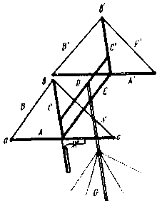
The design of the single-band version of the antenna shown in Fig. 1. To the ends of the carrier traverses E (dural tube 40 mm diameter) attached to a thin-walled duralumin tubes a, A', C and C1 (diameter 30 mm), the ends of which are connected to aluminum or copper wire, In,', F and F' with a diameter of 1.5...2.5 mm Auxiliary cross member D prevents tipping of the antenna and the same as the main cross member E, is attached to a vertical mast G. in addition, Traversa D further strengthens the pipes C and C'.

Fig.1
Pipe And wires In and F forms the active element of the antenna. When the food in the center of the pipe And the antenna will have a horizontal polarization, so the vertical pipe will not affect the performance of the antenna and can not be isolated from the wires In and F at the point V.
The above fully applies to the passive element. If, however, there is strong belief in the symmetry of the currents in the antenna elements, the points b and b' should be insulators.
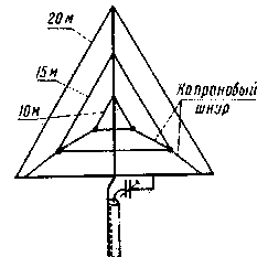
The antenna can be made and how triband. In this case, the elements of the higher frequency ranges are made from wire with a diameter of 1.5...2 mm and stretch with nylon cord inside the elements for a range of 20 m (Fig. 2).

Fig.2
The optimal length triband beam antenna - 2100 mm which is about 0.1 L to 20 meter, 0,15 L, for the 15-meter and 0.2 L, for a 10-meter range, With a passive element on the 20-meter band is advantageous to use as the Director and the rest as reflectors. Then the gain factors and the relationship of radiation forward/backward obtained approximately the same for all three bands, although in this case the maximum of the directivity in the range of 20 m will be rotated by 180° relative to the ranges of 15 and 10 m.
The dimensions of the antenna for the bands 20. 15 and 10 m are shown in the table. It should be borne in mind that the ratios between the dimensions of the pipe And (A1) and wires (B(B') and F(F1) can be changed within a wide range while maintaining unchanged the perimeter of the element. In this case, will naturally vary and sizes of pipe In ('). However, the selected form element - an equilateral triangle is close to optimal and should provide maximum gain.
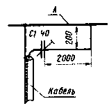
The power of range 20 m is a coaxial cable with a characteristic impedance of 75 Ohms via G-matching device (Fig. 3). The maximum capacity of the condenser C1 - 40 pF, the tube diameter matching device is 10 mm.

Fig.3
The active elements of bands 15 and 10 m are fed via a separate coaxial cables with an impedance of 75 Ohms via balun transformers on ferrite rings. The transformation ratio 1:1.
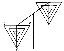
The antenna setup is convenient to carry out in an inverted position (Fig. 4). This may be a work, which, however, reduces the height of the antenna. In addition, there is a deflection of the pipes A and a', And there is also a problem installing guy wires attach a vertical mast G, which can "cling" to the elements.

Fig.4
First, adjust the antenna elements by using a heterodyne resonance indicator, associating it with one or another element near the point at (in'). The length of the wire parts of the elements initially take a small margin compared with those indicated in the table. Her slim when setting up, twisting the wires In (') and F (F') between a point b and at the same time moving the location of twisting along the pipe With upward so that the wires slightly slack (due to deflection of the pipes a and A'). On this configuration feeders should be disabled.
After installing the resonant frequencies (-5% of the average frequency for the Director and +5% for reflector) of all elements of the antenna connect the feeders and a change in the length of the passive components within the small tune the antenna for maximum suppression of the posterior lobe. As the source signal using a crystal oscillator with a horizontally polarized antenna, referred to a distance of not less than 80...100 m. This procedure repeat several times to account for the mutual influence of elements while changing their length.
Sizes
nodes
antenna,
m
Range, m
A, B, F
With
A', B', F'
'
20
7.2
6,2
the 6.75
5,9
15
4.77
4.2
5
4.3
10
3.6
3. 1
3.7
3.2
Next, remove the antenna pattern, and if it is satisfactory, return the antenna to operating position (upward angle). Using the SWR meter to determine the standing wave ratio in the feeders in all ranges, adjust G-matching device.
In the described antenna VSWR is within a 20-meter band after the configuration does not exceed 1.2, and for the other bands was about 1.5. The other parameters were similar to the antenna parameters "double square".
A few words about possible modifications of the antenna. It was noticed that such parameters of the antenna's SWR and the ratio of the radiation forward/backward change within the 20-meter band is much less if I can get the effective diameter of the wires In (In') to F (F') to the pipe diameter And (A'). For this part of the wire elements can perform two parallel wires spaced at a distance of 25 to 30 mm.
Author: S. Bunin (UB5UN), Kyiv; Publication: N. Bolshakov, rf.atnn.ru


