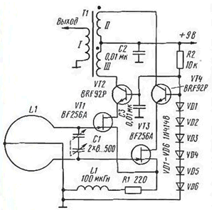
This small-sized antenna (Joachim Schwender. Aktive Schleifanenne fur Empfang. - Funkamateur, 1999, No. 7, S. 787 - 789) operates in the frequency band from 6 to 30 MHz, which ensures the reception of radio stations in several radio and Amateur bands.

The output impedance of the antenna is 50 Ohms. It is a frame (see the figure) that is tuned to the operating frequency of the variable capacitor capacity. Connected to the frame amplifier with differential input, made by kaskadnoi scheme using uni-and bipolar transistors. Application field-effect transistors provides a high input impedance and low input the capacity of the amplifier. The first allows you to fully connect the frame to the amplifier and to realize the highest coefficient before the device as a whole. The second enables cover the large switching bandwidth.
The amplifier used high-frequency field-effect transistors and bipolar microwave transistors with a cutoff frequency of about 5 GHz. When successfully completed output the transformer T1 it allows to obtain a frequency band of the actual amplifier 1... 100 MHz. The transfer coefficient with its entrance on the 50 Ohm load is about 1. The throttle L1 in the circuit drains of field effect transistors VT1 and VT3 are included to increase the input resistance of the amplifier in the high frequency edge of the band of operating frequencies of the antenna.
The voltage at the bases of bipolar transistors (about 4 In) stable the chain of diodes VD1 - VD6. Apply here Zener impossible, as they generate in the stabilization mode high frequency noise can negate all the advantages of the amplifier.
The amplifier consumes less than 3 mA, so it can be fed from compact battery voltage 9 V (domestic analogue "Krona". "Emery").
Transformer T1 is made on the annular magnetic core size To 13x7,9x6,4 mm ferrite initial permeability 800. Winding I contain 3 coil and the windings II and III - 20 turns. Wire - high frequency Litz wire.
The frame is made of copper tube with a diameter of 16 mm and is ring shaped with a diameter of 1 m with a slit, in which a variable capacitor C1. It is taken from broadcast receiver. The findings from the stators are connected to the frame and the rotor or to what is not connected. This minimizes the impact of the hand when setting the antenna on the operating frequency. Because the ceiling near the antenna frequency is large, and the frame high quality, variable capacitor should be given a good Vernier device and at least a simple scale.
Structurally, the frame is fixed vertically on a wooden base on which set the capacitor C1 and the other elements of the amplifier and battery with a switch (not shown). The top of the frame is supported vertical wooden stand. Along it to the amplifier is a wire tap from frame (it needs to be done accurately from its middle).
The quality framework at a frequency of 6 MHz to about 1000. It provides high the transmission coefficient of the device in General, and good filtering of interfering signals radio stations. However, if the reception interfering station has the strongest signal and running at a frequency close to the resonant frequency of the antenna, amplifier manifest nonlinear effects. Since the frame has a spatial selection, then such problems can be eliminated partially optimal orientation frame.
Author: Joachim Schwender


