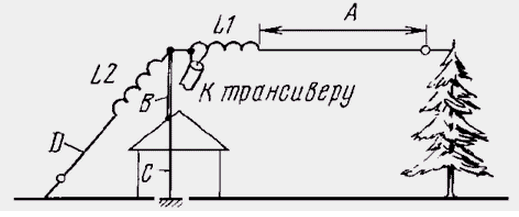
This antenna can be used in cases where there is not enough space to install a full-sized dipole on 160m. It should be noted, what, are calculated using the relationships given in this article, similar shortened antennas can be made on other Amateur bands.

The antenna consists of (see figure) emitter length with A lengthening coil L1. This coil "lengthens" the transducer to electrical length , and in "earth" is used mast B and grounded armature C of the building. For improve the efficiency of the antenna, if possible, it would be good to install shortened opposed to D with a lengthening coil L2. Better if balances there will be several.
The calculation of the antenna is produced in such sequence. Defining the length of the radiator A (m), choose the resonant frequency of the antenna f (megahertz) and the diameter d of (meters) wire, which will be made of the emitter. The following example of calculation will be used the following values of these parameters: A=29 m, f=1,86 MHz, d=0,0015 m (1.5 mm).
First, determine the wavelength  (meters) for a selected resonant frequency antenna, its working angle
  (degrees) and the intermediate parameter S:

For our example -  Then find the characteristic impedance Z (ohms) the antenna conductor and the corresponding reactance of the antenna in XC the connection point of the inductor L1 to the canvas of the radiator:

For our example, Z=600,6 Ω and Xc =And 283.8 Ohms. Note that reactive the resistance of the shorted emitter capacitance. Therefore, to tune the antenna in resonance is used, the inductor L1. Its reactance XL must be numerically equal to the reactive impedance of the antenna Xc . The inductance coil L (microhenry) is calculated by the formula:

For our example, L=24,3 µh.
Braid power cable connected to the left (in the drawing) end of the coil L1, and its center conductor - to withdraw from this reel. Connection point (n1 turns counting from the left end of the coil depends on the wave resistance power cable R, the inductive reactance of the extension coil and the number of its of turns n. They are connected by the relation:

If, for example, lengthening the coil L1 has 28 turns, and an impedance cable 50 Ω, the center conductor should be connected approximately to the 12th a coil. More precisely, the connection point is determined experimentally by low SWR in the supply feeder.
Lengthening the coil is calculated according to standard formulas. Because when you work on it occurs high RF voltage, the coil is better to make a single layer with involuntary step of winding equal to the diameter of the wire used to the manufacture. This wire should have a diameter not less than 1 mm.
Lengthening coil can to perform and annular magnetic core of carbonyl iron, if the transmitter has a small capacity, and the diameter of the magnetic core will be a few centimeters.
Author: K. Bottcher


