Dimensions full-size antennas on 160 m encouraged to seek acceptable the decisions you cut them. The author, for example, prompted by the sad the fact that a full-sized dipole Inverted V on the mast reasonable height (12 m) does not fit the dimensions of the roof panel model home. Rather, fit, but so that nothing good on this placement does not have to wait - the last few meters (5-7 m) on each side of the dipole is almost lying on the roof.
The height of these extreme lengths above the roof is 0.5...1.5 m, what is wrong at least for two reasons:
1. At the ends of the dipole develops a large voltage that a serious power can lead to unfortunate occasions when you accidentally touch them the people working on the transmission antenna;
2. Typically, on any roof along it at a height of about 2 m are different wire - lighting, Elevator cables, relay, etc., which absorb all that is radiated by the antenna parts, which are placed below these wires. By the way, the same circumstance is the cause of unsatisfactory performance of various wire antennas hanging between condominium and located entirely below the level of the roofs, as particularly strongly absorbed radiation at small angles to the horizon needed to work on DX-tracks. In addition, this placement can cause TVI.
Thus, it is necessary that the ends of the antenna were at least 3 m above the roof. If you have the opportunity to put on the edges of the roof, two additional masts with a height of 3 m, then do so and on this article can not read.

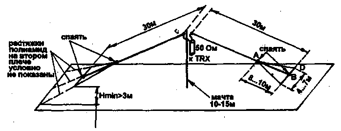
If this is not possible, an acceptable alternative is shown in Fig. 1. Almost without reducing the efficiency has managed to reduce the overall length of fabric from 76 to 60 m, which allowed to raise the lower edge to a height of 3 m mounting polyamide stretch over the railing of the roof. Shortening is achieved by capacitive loads at the ends of the dipole, made in the form of "dopaste oars." The implementation of capacitive loads with a gradual increase in the width of the shoulders of the vibrator (without discontinuities) provides a smooth, without abrupt changes, the change in impedance, better matching of the antenna with room to spare, and as a result - higher efficiency compared to the classical version of run-capacitive load - ROM or a set of radial wires on the thin end of the vibrator. The dimensions of the capacitive loads in Fig.1 should only be considered as indicative, as in the configuration process, they can seriously change.
For convenience of manufacture and adjustment of the antenna is necessary that the mast is securely attached stretch marks and stood firmly with loose vibrators. In addition, provide the ability to work a soldering iron if not across the roof, then at least at the base of the mast. It is convenient to observe the following procedure for installation and configuration.
1. Rises and secured with stretch marks (Fig. 1 is not shown) mast with pre-attached the power cord and the two arms of the vibrator a length of 30 m each, made of copper wire or Antenna cord with a diameter of 2.5...4 mm., the Top node is the same as a conventional full-sized antenna.
2. Departing from the hanging edge of the vibrator 10 m, it is soldered two additional wire length of about 14 m each (point a), and the ends of these wires connect by soldering the end of the vibrator (heat In). Additional wires are small mechanical stress and can have a diameter of 1.0 to 2.0 mm (non-critical). After that stretch polyamide cord capacitive load is formed into the shape shown in Fig.1. There is no need to withstand the correct shape of triangles and place all three wires in one plane - make the way easier for local conditions, focusing on the dimensions shown in Fig.1. They do the same thing with the second half of the vibrator, which has the same dimensions as the first.
3. Roughly (with an accuracy of about ±100 kHz) adjust the resonance frequency of the antenna (the frequency at which the observed minimum SWR) by changing the length of the extra wires and re-performing the soldering points and attachment points C and D simultaneously in both arms of the vibrator.
4. If in step 3 you cannot achieve the desired result, will have to change the size of a And B. Its increase leads to a decrease in the resonant frequency, the shortening is increased.
5. For fine adjustment of the resonant frequency (within ± 100 kHz) without changing the length of the extra wires move the point of attachment of the lateral stretch C and D. the shape of the capacitive loads of the triangle may be closer to rhombic, which is quite acceptable. At this stage it is necessary to achieve not only a predetermined resonant frequency, and minimum SWR on it. To do this, you may have different ways to find points C and D on the left and the right half of the vibrator.
This antenna has the following advantages:
- reduced size and large suspension height of the edges;
- capacitive shortening leads to the smallest of all the ways of shortening reduced efficiency;
- does not require concentrated superstructural elements;
- the setting is very comfortable and is held at the bottom - at the level of the roof that is not required to work on the mast.
The tuned antenna has a VSWR at resonance < 1,2 and bandwidth of 90 kHz level VSWR<2. 1.5 summer months on this antenna worked more than 80 countries for DXCC on all (except Australia) continents.
Publication: N. Bolshakov, rf.atnn.ru


