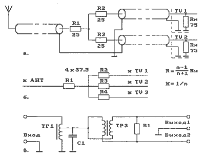
In Fig. 1 shows the schematic of the matching antennas to multiple receivers: УSW-radios and TVs. With antenna connections are made through standard 75 Ohm coaxial cable. Harmonization antenna with multiple receivers of radio signals is possible with relatively simple resistive dividers, and with the help of a rather complex circuits using in its composition, RF transformers, RF chokes, etc.

Fig. 1 wiring connection to the antenna to several receivers (УSW and TV):
and two,
b - three or more,
in two low attenuation.
In Fig. 1.and a diagram of the optimal connection to the antenna to two receivers (УSW-radios and televisions) with the divider resistors.
In Fig. 1.b shows a diagram of the optimal connection to the antenna three or more receivers (УSW-radios and televisions) with the divider resistors.
Matching circuit of the antenna and multiple receivers using the divider resistors, of course, simple, but greatly attenuates the desired signal. This often requires subsequent amplification with an antenna amplifier. The weakening of the signal from the antenna can be reduced with the use of appropriate schemes of initiator to the high-frequency transformers.
In Fig. 1.in the presented scheme the optimal connection to the antenna to two receivers (УSW-radios and televisions) scheme using RF transformers. This scheme ensures the transfer from the antenna to the receivers of signals with larger amplitude (larger share) of the radio signal, i.e. agreeing with the antenna is accompanied by a smaller loss of useful signal.
Publication: www.cxem.net


