


")

When receiving television or УSW stations for each of the frequency ranges necessary a separate antenna. Combining the signal from the antennas, located, for example, on the roof or on the attic, in a special filter, can't let them down with the inputs antennas to one receiver General cable. In practice, most is the most simple a filter having inputs УSW and UHF, as well as overall output. In the circuit УSW the filter is used bottom frequencies (upper cuts), and in circuit UHF filter top frequencies (lower cuts). In past manufacturers made to each The TV receiver such small box. The most important accessory serious receiving stations is collective filter with many inputs. It gives you the opportunity to combine the signals of the individual powerful antennas, including radio signals УSW (CCIR). One possible solution this task is shown in Fig.1.
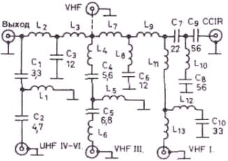
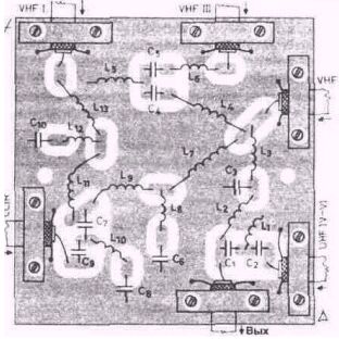
Top the entrance, marked as "VHF", which is broadband can be used, for example, for TV-dx; you can connect turning the antenna. The described filter is not designed to accept a "provimento" range OIRT-УSW (66 MHz…73 MHz). If not required in the input CCIR-УSW, you can simply delete all L - and p-elements, to the right of L9, at the same time increasing the number of coils L9. It will then input VHFI. Printed fee filter and schema place parts on it shown in Fig.2.
Coil made of copper wire (preferably silvered) with a diameter of 0.5 mm and have a diameter of 3 mm. L1 contains 2 turns; L2 - 5.5 turns; L3 - 3,5 revolution; L4 - 6 turns; L5 - 4,5-loop; L6 - 4,5-loop; L7 - 7,5 coil; L8 - 4 revolution; L9 - 4,5-loop; L10 - 11,5 coils; L11 - 15.5 turns; L12 - 6,5 coils; L13 - 10.5 turns. All details are on the circuit Board from the side foil. Response from inputs collective filter to it total output is shown in chart.
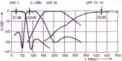
As can be seen, the width of the passbands for rated the frequency is large enough, therefore, most likely, will not be need to tweak coils. We also note that, as it is easy to verify by experiment, the maximum attenuation at a frequency of about 50 MHz in the radio УSW due to the chain C7-C8-C9-L10 (one of the pole frequency). The lowest point at about 85 MHz on the curve of the VHF range, I (the second pole frequency) occurs due to the chain L11-L12-L13-C10. Nominal impedance connection points coaxial cables (75 Ohm). Inputs that are not used, you need to load bezindustrialny resistors 75 Ohm.
Literature
Publication: www.cxem.net