


")

This is the conclusion I have come gradually. But here's the thing. To view TV shows are most commonly used active combo M/DM In antenna (AKA) with reduced size. Many designs AKA can be divided into two group: for external mounting (outer) and internal (room). Installed I have in my window at the level of the 4th floor of a brick building AKA provided satisfactory reception of all programs in the UHF channels and channel 11 MB (12 of 15 programs broadcast in Tyumen), which is not true of the remaining 3 programs on the MB (1, 3 and 9 channels). Especially the "suffering" (3 channel: multiplanimetric images due to multiple reflections of the signal sometimes led to full incomprehensibility of the picture. The same "disease", but only to a lesser extent, was observed on 1 channel And the signal on channel 9 came with an insufficient level and the TV was collected because of this different kind of clutter Like this to fight? Having some experience with baziruemym chains and having worked in his time material the interference suppression [1, 2], decided to experiment.
For a start, purchased in radio shack TV-adder signals (Splitter) "BLACKMOR C3" with two inputs MB and one UHF. and second AKA (MV/UHF) in room the performance, which is a combination of automatic process 6-cell antenna dipole UHF and MB simultaneously Including through the adder both antennas, found that most efficiently on all channels "combination" works when the inclusion of outdoor AKA the nest adder "UHF". a room in one of the nests "MB". Food was served on both antennas.
During the experiments outdoor antenna remained in a fixed position, aimed at the telecentre, located at a distance of 10 to 12 km Room antenna moved: changed its orientation in azimuth, elevation and polarization. These manipulations allowed us to obtain an image with very high quality without megacontract and interference on all 15 programs, but, unfortunately, in different positions room AKA. Especially critical was the conditions for low-frequency channels (the same 1. 2 and 9 MB). But compromise the installation location AKA (with some degradation of the image quality on certain channels) still can be found Impact that the system of two AKA may to some extent to suppress clutter. if you operate an incremental signal (due to the action of ARU TV) and using a phase method of noise compensation described in [1.2]. Not should be discounted and the difference frequency response of the adder inputs.
If you want to receive TV signals from different directions, then you need rotate and outdoor antenna. Ways to rotate the antenna a few:
- manual-using mechanical gear;
- Electromechanical (motor and reducer),
- e - the change of antenna phase-shifting elements.
I want to note one important feature: the system AKA how photocomposition (common mode) will only work on a small distance K from each other (what higher the frequency, the the distance should be less) to comply with the terms phase summation of the signals from both antennas. At a great distance AKA on the screen the TV may occur a fatal loop and, under certain conditions, even the failure of synchronization. In this case it is better to include through the adder two indoor antenna (if the signal level of the television center in place admission). Spreading their e space and mutually orienting, can be accounted for clutter, increase the signal and improve reception quality of the desired program.
For long-distance reception of TV signals can be collected from AKA something similar to phased antenna array (PAA), i.e. to position the antenna as common-mode elements in the same plane and at a certain distance from each other, depending from the frequency. The signals from each ASC shall be consolidated in a common cable reduction through the adder, the power amplifiers AKA is made through cable or separate wires To suppress clutter AKA one of (auxiliary) is sent to the source. The position of this AKA is selected according to the maximum to suppress interference, the signal which is out of phase with the signals from main AKA. If to be exact, for the complete destruction of interference still and amplitude balancing signals. I don't think it will be an insurmountable obstacle for someone who decides to "finish off" once and for all annoying hindrance.
When experimenting with antennas, will likely have to rotate and the outer antenna. If it is placed near the window, I can recommend a simple the rotation mechanism, which in the times of his youth "assembled" from a friend radio Amateur.
In Fig.1 schematically illustrates a rotary module with manual transmission. It consists of the mast on which the antenna is attached, a gear with a frail 90° rotation, an elongated the axis of the pulley and pivotally connected to a wooden pole.
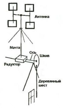
Fig. 1
To rotate the antenna enough to put a hand in the little parcel which hangs in front of the pole end, to take the pole arm and slightly tilting, to make a reciprocating motion (up-down). Resulting from the pole and kind of pulley crank the mechanism (like the wheels of a steam locomotive) converts the aftershocks of the pole in a rotational the movement of the shaft, which via a gear with the deceleration is transmitted to the antenna mast. On after half a century it is difficult to judge some of the construction details, but here the main thing - idea! Indication of the position of the antenna can be implemented (along with other ways simple mechanical revolution counter.
Author: V. Besedin, Tyumen