There are many types of microwave antennas - parabolic, phased arrays, on the basis of Fresnel lenses, etc. in Relation to home made PA recommended due to the ease of their manufacture.
There are two versions of the PA:
by vyklicky on the matrix;
- soldering of copper wire and mesh (i.e. mesh antennas).
Each antenna has its advantages and disadvantages. The advantages of the first is simplicity of shape control during manufacturing, the second - less weight and windage.
You first need to determine what the feed available to the radio Amateur. Refer to Fig.1 and identify which characterize the antenna. First, it is its diameter d (as a rule, they are set at the beginning of the calculation). The shortest distance from the antenna focus (the focus is the Converter feed or the second mirror in the case dvukhdetektornoi system) before .reflector antenna is called the focal length f. The depth of the mirror h is the greatest distance from the plane of the aperture of the reflector to the reflector antenna. The angle of aperture of f - the angle at which the visible plane of the aperture antenna reflector S from its focus F. In this case they are connected by the following relations.
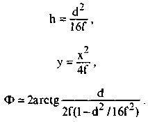
The ratio f/d defines the parameters of your radiator. Usually f/d is in the range of 0.3 to 0.5. The larger this ratio is, the smaller h, and the lower the consumption of materials for the manufacture of PA (with some loss of gain Ku). If you have a radiator with f/d=0.3 and want to reduce costs then you can buy a radiator with f/d=0.5, and it is best to buy irradiator with a variable f/d.
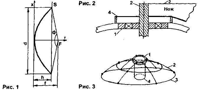
First, according to the formula (2) calculate the dependence of y on x (taking values from 0 to d/2) and create the table. The resulting value is transferred to the graph paper and construct a parabola. Further, it is adhesively bonded to the steel sheet 5 mm thick and cut out along the line of a parabola. Thus the knife (you must strictly adhere to its form, since this largely depends on the final result and the quality of the PA). Then, in accordance with Fig.2, should pick up the rod 2 and the bearing 1 of suitable size (3 - knife). This knife is pruned by half the diameter of the rod 2 and is welded thereto coaxially. In accordance with Fig.3 frame is made from steel rod with a diameter 8...10 mm (welding). While the ribs are approximately 2 arch on the knife. In the top of the frame vparivayut bearing.
Set the frame on level ground, bearing 1 (Fig.3) you must plumb the pipe 4 with an inner diameter larger than the diameter of the bearing 1. All the space under the frame is filled with gravel or broken bricks.
By means of a bearing washer 4 (Fig.2) with a diameter slightly larger than the diameter of the bearing, and a height equal to the thickness of the future of the PA (e.g. PA with a diameter of 2 m thickness equal to 25 mm), is inserted in a bearing knife. Mix concrete mortar cement-sand to thick consistency, put it into the frame and level with a knife. Dried the resulting matrix for 3 ~ 5 days. On the third day (when the weather is dry) RUB clean cracks alabaster and smooth out with sandpaper, controlling the quality of the surface with a knife. It should be noted that if you plan to use the matrix repeatedly, put between her and the ground two or three layers of roofing material, so that it is not destroyed by moisture. Also I do not advise to use the recommendation from [2] for the manufacture of a matrix of clay, because this material when drying gives a lot of cracks, and the resulting matrix is short-lived.
Next, proceed to Vileika antenna. There are many ways to perform this process. Here are a few tips. First, if you wycliffite antenna of large diameter, remember three drawbacks inherent to it - a lot of weight, wind resistance and low strength. To simplify the manufacture'll split the antenna (exactly) 6...8 sectors (note the form of their compounds, bonding). In this case, the matrix can also be done as a sector, but it is preferable to make it completely because it can be vilayati offset antenna. For strength increase thickness of the reflector and armywide its radial ribs of steel wire.
As a material for vyklicky PA usually take fiberglass, cut into strips, and epoxy glue. You can use the technique described in [1], several simplifying it. First washed with soap matrix is applied to the separation mixture, which is used as motor oil (the best result is obtained if before that grate the matrix even layer of mastic for flooring). The puck 4 (Fig.2) firmly insert the tube, which loosely put another puck out of duralumin, which has a height equal to the thickness of the reflector. Next, put a layer of resin (without damaging the separation of the mixture) and place the pieces of fiberglass, smoothing them and removing air bubbles. Of course, it is desirable to use metallic fiberglass, but you can use ordinary, due to malodostupen first. In the future (after manufacturing), you need to paste the reflector pieces of aluminum foil, cut sectoriales. Still the first option, reinforced with fiberglass, is preferable due to a better surface quality. Another option is the formation of the conductive surface is applied to the reflective surface PA of colors, which include metal-powder Foundation (silverfish, etc.).
Increasing the thickness of the reflector to the required size, preformative nuts to attach the strap. You can also frame on which is mounted a reflector that is welded to the radial ribs that secure the reflector. The reflector can also be secured with bolts through holes drilled in PA after it dries. Antenna with a small diameter can be made of papier mache (the idea was suggested by R. K. Hagenowii). The filler is taken for the newspaper. They are soaked in water and passed through a meat grinder. Add to the resulting mass Wallpaper glue as a binder material. The resulting mixture is applied to the matrix (previously causing her separation the mixture and level it with a spatula, forming the desired surface. After drying, remove the antenna and cover the conductive layer and several layers nitropaints to protect the PA from an atmospheric precipitation. Instead of Newspapers you can use fabric as described in [2], forming the PAS as in the case of fiberglass, using as binding material Wallpaper glue.
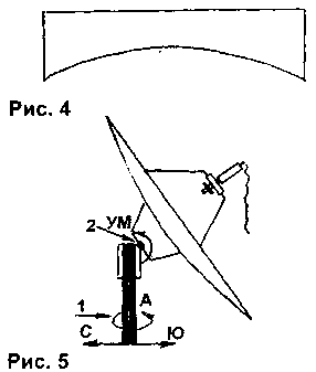
The second option PA (net) described in [3]. For it made a template (Fig.4), the parameters of which are calculated according to the formula (2). It radial curve of a parabola from thick copper wire. Wire thickness is selected based on the diameter of the antenna. For example, for antennas with a diameter of 1.5 m. take the wire with a diameter of 4...5 mm. Also it is necessary to make a circular belt. The diameter of the zones varies with step 10...30 see the soldering points of the zones of radial polynomials are computed by the formula (1). After fabrication of the frame it fit fine-mesh copper grid, which is soldered to it. It should be noted that the larger the diameter of the PA, the thicker the wire from which it is made, and the harder it is to solder (if you are using wire with a diameter more than 7 mm is desirable welding).
The next step is the manufacture of slewing bearings (slewing rings). All SDAS are divided into two types: azimuthally pomestie and polar.
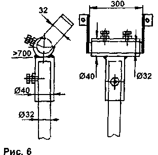
The first type is easier to manufacture because it uses only two adjustment axes (when migrating from the satellite to the satellite uses both). The first axis is azimuth, and the angle is calculated by the formula

where f is the longitude of the place of reception in degrees, Fizz - the location of the satellite in orbit, in degrees, w is the latitude of the place of reception in degrees.
If you point the antenna due South, then to tune to the preset satellite azimuth you need to take away from A 180°. If the angle is positive, the antenna offset by the value of this angle to the Western side; if it is negative in the East.
The angle of pomestnoy axis 2 (Fig.5) is calculated by the formula

Suspension design is arbitrary. Its dimensions depend on the diameter of the antenna. For example, the antenna diameter of 1.2 m SDAS are made in accordance with Fig.6.
The specified type OPU is used primarily to offset the PA and PA axial-symmetric small diameter. Because of the large format antenna have more weight, they are hard to rebuild about two axes. So they use different type SDA - polar (Fig.7). It has four axes of rotation a - A (1), MIND(2), polar (3) and corrective (4). For orientation of the antenna it is necessary that the plane, which belongs to the polar axis and the axis of the reflector, lying in the plane of the azimuthal axis 1 and the direction to the South, marked at true noon. To determine the direction hammered into the ground a small pin, and every 20 to 30 minutes note the position of the shadow cast by the pin. The shortest distance from the end of the pin, driven into the ground, until the lines traversed by the shadow of the end of the pin, and is towards the South.
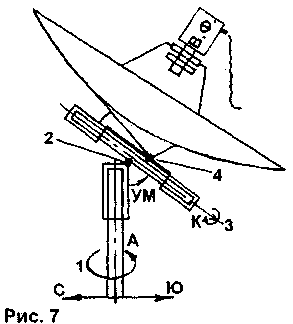
Next, set the angle to the axis of the MIND (2) is equal to the geographical latitude of the place of reception in degrees. Establish the corrective angle To the axis (4)

Then the polar axis (3) turn on angle

where f is the longitude of the place of reception; Fist - the location of the satellite in GEO (if VD (Fiss>0, if z.etc., we Piss<0).
As you can see, in the case of polar suspension to rebuild from the satellite to the satellite is only used polar axis (which gave the name to this type SDAS). Therefore, simplifies the reconfiguration of the antenna. The adjustment range is within ±40° relative to the South. But for ease of use pay the increasing complexity of the pan-tilt mechanism.
In Fig.8 shows one of many options polar SDAS.
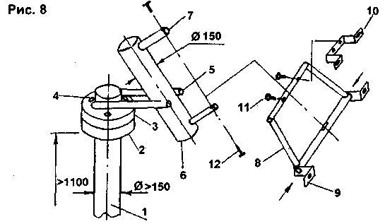
The sizes are specified for PA with a diameter of 2 m. the pipe 1 is welded to the flange 2. The top fits over the flange 3, which rotates freely around its axis. The flanges have holes for 4 of their mutual fixation. The upper flange is welded two pipes 5 with a diameter of 40 mm and a length of 60 cm. these two tubes bolted pipe 6 length 80 cm To the pipe 6 is welded two pipes 7 having a diameter of 40 mm and a length of 25 cm pipe 7 is attached to the line 8 by means of screws 12 (trapezoid made of pipes with a diameter of 25...32 mm). To the trapeze by clamps 9, 10 (extremely strong) is attached to the reflector of the antenna, while in the lower pipe trapezoid insert the pin with threads on the end, and the bracket 10 is attached to the top tube of a trapezoid by means of screws 11, which is regulated by the correction angle. Pomestnaja and polar axis can be regulated with Talipov (not shown for simplification). It is important to arrange them so that they are accessible and do not interfere with access to the Converter having apatouria irradiator. I do not advise to fit every positioners, actuators and other means of remote configuration, the use of which is justified only in the case of using a small PA. In the manufacture of PA it is necessary to provide a minimum clearance of all connections, because the bumpiness of the antenna in the wind is bad at the reception, and also leads to rapid destruction of the tumor.
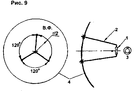
For mounting the Converter to the antenna in accordance with Fig.9 in the reflector drilled three holes. Made from duralumin ring 1 with an inner diameter equal to the diameter of the neck of the Converter. The ring may consist of two parts, connected together by bolts. In the ring drill three holes 3 and cut them in the thread. Aluminum (tubes) are made of three rods 2. Their size is chosen so that the ring 1 defended from the focal point F 2...3 cm At the ends of the rods are cut into the threads and screwed them into the ring 1, and then attach them to the reflector 4.
The gain of the received antenna is calculated by the formula

where Q is the utilization factor of the surface (KIP), for most types of irradiators Q=0,4...0,7 (usually 0.6);
L - length of the received wave.
The table summarizes the Ku antennas three diameters on most ranges used (Q=0,6).
As we can see, the higher the frequency, the more the Ku antenna. But under the current situation (the satellites have approximately equal effective radiated power) at different attenuation of signals on the track of the satellite - Earth (at higher frequencies the attenuation is greater) the resulting signal at the receiver input at different ranges are approximately the same.
Another interesting fact that in the catalogues of many firms that trade PA, indicated clearly too high Ku. Able to independently verify, considering KU according to the above formula.
Table 1
fo, GHz
17,5
11,5
3,9
2,6
0,72
d, m \ L, m
0,017
0,026
0.077
0,115
0,417
0,6
38,7
35,0
25,5
22,1
10,9
2.0
49,1
45,4
36,0
32,5
21,3
5,0
57,1
43,9
43,9
30,5
29,3
The table also shows that at low frequencies the use of PA is impractical due to lower compared to the phased array antenna Ku.
Here are a few tips.
1. The larger the diameter of the PA, the narrower its directivity, so close to a large antenna, it is desirable to install a small diameter antenna and set it on the satellite with the highest signal strength in your area. Then, noticing the approximate direction to the satellite, to send in the same direction the larger dish. Taking the signal, to adjust the position of the feed into the focus of the antenna for the best reception of weak image channels.
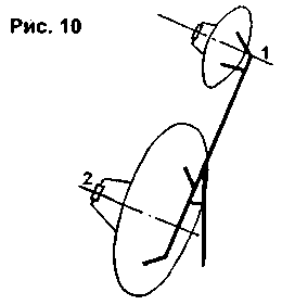
You can simplify the migration of large antennas, having strengthened a little on the edge so that the axis of rotation PA 1, 2 (Fig.10) are parallel. In the scheme of mounting a small antenna you must enter the adjustment screws to adjust the parallelism of the axes of the antenna. Taking the signal to a small antenna, switch to a larger one.
To fine tune to the satellite (even with very small signal) very convenient to use special detectors, the schema of which were published in Amateur radio literature. For this purpose you can use the spectrum analyzer (in the range 1 to 2 GHz), as shown by the signal from the Converter through the coupling capacitor. Thus one should not forget to file for Converter supply voltage +V. 14
2. Should be thoroughly grounded antenna and Converter to avoid damage to your equipment during a thunderstorm (judging by the statistics, it happens quite often). For this wound on the connector that connects the cable with the Converter, 2...3 coils of wire with a diameter of 1.5...2 mm, and grounded him. The same ground wire (separately and in parallel on a single circuit) metallic surface of the antenna and ODU.
3. Don't forget that the larger the antenna diameter, the greater its resistance to the wind, so there should be measures to protect the antenna and ODU from wind loads. Use for the manufacture of SDAS quality rolled steel. For example, if meter PA required carrier pipe diameter 32...40 mm, two-meter - 120...150 mm. If possible, mount the antenna so that her back side was defended by a wall. If possible, avoid installing the antenna on top.
In conclusion, I note that this article describes only a small part of antenna systems.
Personally thank V. V. Orlov and S. A. Kozlov for their help in the fabrication drawings provided in this article.
Literature
Author: V. Fedorov, PGG. Lev Tolstoy, Lipetsk region; Publication: N. Bolshakov, rf.atnn.ru


